Now that we have a simple skeleton, it’s time to bring up some peripherals. It’s probably not the most important, but of course we want to start with the LED/capacitive touch display. It’s shiny!
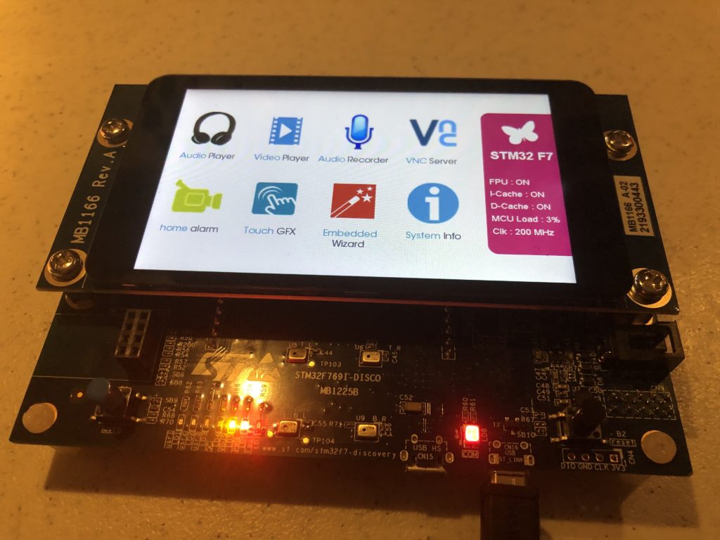
A good place to start when you are trying to figure out how to do or use something in software is often to look at a sample that already does what you want. Our evaluation board originally came with a really nice demo already installed:
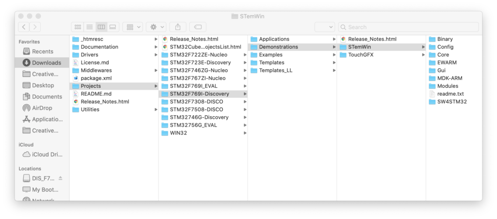
And the source for this demonstration is included with the STM32-Cube MCU package:
But if we look at this project (I’m cheating and using the commercial IAR tools and the project folder (EWARM) that ST included), we hit a few snags:
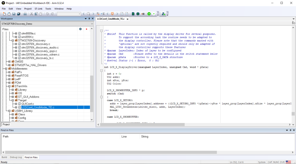
The LCD isn’t supported at a clean, stand alone driver level in this code. Those (audio, qspi, sdram, ts) are in the folderSTM32769I-Discovery. LCD support is in “LCDConf_CmdMode_TE.c” buried in a folder under Middlewares / STemWin.
To cut a long story short, emWin is an GUI library for embedded products developed and sold by Segger. It is sold as C source code for $3,000 – $12,000 under a license agreement where you don’t share the source.
STemWin is a version of emWin that ST licensed and distributes in library form. The C file above is a display device driver written to be compatible with STemWin/emWin.
I’m sure that STemWin is fine, but I really don’t like relying on object only libraries. Among other things it really hampers your ability to track down and fix bugs. So, we aren’t going to use STemWin and we sure as hell aren’t going to give a German company $12,000 for software I can’t share as source with you!
On top of everything else, for reasons that I’ll explain below, the demo won’t build and run quite as expected from the IAR debugger for us to investigate what is called and in what order. Still, being familiar with writing device drivers and the ST peripherals involved, I could cobble together a stand alone driver from the example, but we don’t have to:
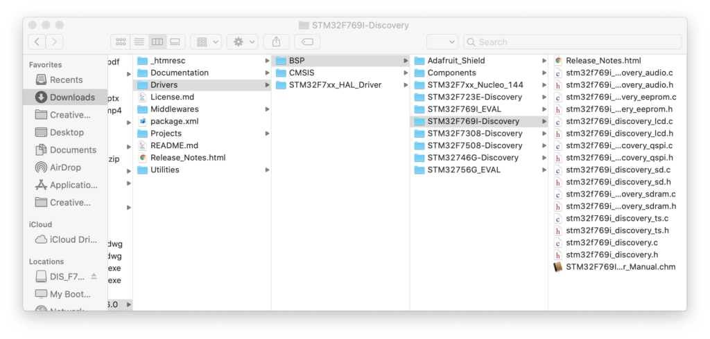
In the same package as the demo source is a folder called drivers with a subfolder for “BSP” (presumably ‘board specific peripherals’). If we select our eval board we can find a .c and .h file for the LCD display.
We can literally drag these files to our project in Eclipse and Eclipse will offer to make a local copy and add them to our project for compilation. But, we will find that there are usually the same few steps required to make this work.
- Copy the desired ST driver over
- Try to compile
- Use the errors to find the additional driver(s)/file(s) you need to copy over
- Flatten the include paths hard coded into ST provided files
- Repeat 2-4 until you only get linker errors
- Enable the missing parts of HAL library to get rid of the linker errors
- Go back and tweak code and/or use pragmas to get rid of any warnings
The LCD driver is a good example of this. It relies on another BSP driver for SDRAM, some component specific drivers (ex. otm8009a.c, adv7533.c, etc.) and a simple font system with the fonts each in an individual .c file. A number of these files use complex relative include directives like this:
/* Includes ------------------------------------------------------------------*/
#include "stm32f769i_discovery_lcd.h"
#include "../../../Utilities/Fonts/fonts.h"
#include "../../../Utilities/Fonts/font24.c"
#include "../../../Utilities/Fonts/font20.c"
#include "../../../Utilities/Fonts/font16.c"
#include "../../../Utilities/Fonts/font12.c"
#include "../../../Utilities/Fonts/font8.c"
The ../../../Utilities/Fonts stuff is hard coded to the complex folder structure of the STM32-Cube package. We don’t have that. Including .c files for indirect compilation (what’s going on with the .c files) is a technique to be used with care. We won’t use that here, so I changed this to:
/* Includes ------------------------------------------------------------------*/
#include "stm32f769i_discovery_lcd.h"
#include "fonts.h"
// .c font files used are just added and compiled to the project normally
// so no reason to include here
//#include "../../../Utilities/Fonts/font24.c"
//#include "../../../Utilities/Fonts/font20.c"
//#include "../../../Utilities/Fonts/font16.c"
//#include "../../../Utilities/Fonts/font12.c"
//#include "../../../Utilities/Fonts/font8.c"
Once all the pieces are in and compiling correctly, we start getting linker errors for HAL library functions that can’t be found. That is because, although the entire HAL library was included in our project when we created it, a bunch of the .c files were set to be excluded from compilation by default.
To fix this we find the needed file, which is in the tree but greyed out, right click on it, and select “Properties”:
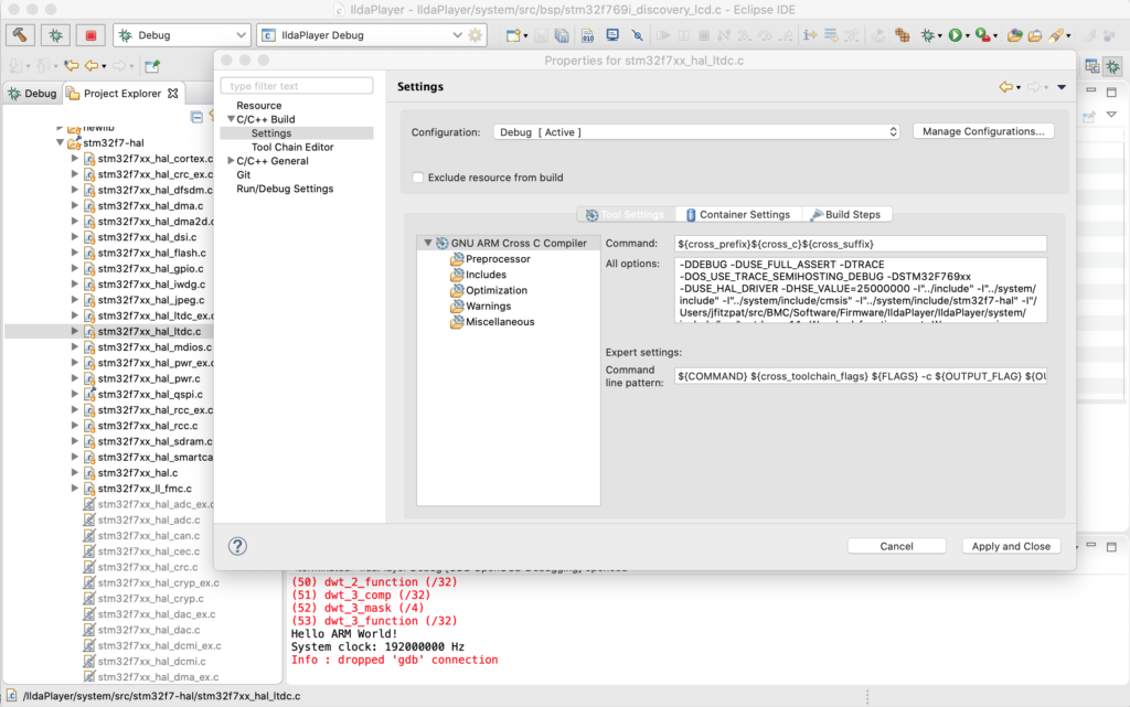
Under C/C++ Build / Settings make sure that the “Exclude resource from build” checkbox is unchecked and the needed HAL file will now be compiled with our project.
Eliminating all remaining warnings is just my thing. If you don’t, how will you know that something you just pulled from a git repo compiled correctly? In this case a number of the files throw warnings for unused variables, which I eliminated with #pragma statements, for example:
#pragma GCC diagnostic push
#pragma GCC diagnostic ignored "-Wunused-parameter"

__weak void DSI_IO_WriteCmd(uint32_t NbrParams, uint8_t *pParams)
{
  /* NOTE : This function Should not be modified, when it is needed,
            the DSI_IO_WriteCmd could be implemented in the user file
   */
}

#pragma GCC diagnostic pop
Digging deeper and understanding the hardware and peripherals involved with the LCD display is well worth doing. The primary connection is something called DSI (digital serial interface), a standard from MIPI (Mobile Industry Processor Interface Alliance). ST has an app-note on their integrated DSI host controller here.
In addition to the DSI communication peripheral, the LCD driver we are using utilizes two other peripherals built into the MCU. LTDC, an LCD-TFT display controller, and DMA2D, a special direct memory access controller for common operations in 2D graphics (like converting between color spaces). You can read about both these peripherals in the Reference Manual for our MCU.
There are some differences between the driver in the STemWin demo above and this standalone driver that we will be considering a little down the road, like the tradeoff between color spaces used and SDRAM spaced needed, but for now let’s just make something happen!
With everything compiling we still need to initialize and use the driver, so I made another module called Display.c. To start, we can make our display_Init() look like this:
void display_Init()
{
	// Initialize in Video Burst Mode, bail if we rail
	if (BSP_LCD_Init() != LCD_OK)
		return;

	// Initialize our background layer, using SDRAM
	BSP_LCD_LayerDefaultInit(LTDC_ACTIVE_LAYER_BACKGROUND, LCD_FB_START_ADDRESS);

	// Select and clear to black
	BSP_LCD_SelectLayer(LTDC_ACTIVE_LAYER_BACKGROUND);
	BSP_LCD_Clear(LCD_COLOR_BLACK);

	// Now do the same for the foreground layer, but make white
	BSP_LCD_LayerDefaultInit(LTDC_ACTIVE_LAYER_FOREGROUND, LCD_BG_LAYER_ADDRESS);
	BSP_LCD_SelectLayer(LTDC_ACTIVE_LAYER_FOREGROUND);
	BSP_LCD_Clear(LCD_COLOR_WHITE);

	// Let's throw in a string
	BSP_LCD_SetTextColor(LCD_COLOR_RED);
	BSP_LCD_DisplayStringAtLine(10, (uint8_t *)" Danger Will Robinson!");

	// And a couple of rectangles
	BSP_LCD_SetTextColor(LCD_COLOR_BLUE);
	BSP_LCD_FillRect(10, 10, 600, 50);
	BSP_LCD_SetTextColor(LCD_COLOR_YELLOW);
	BSP_LCD_FillRect(500, 70, 250, 320);

	// Adjust brightness
	// BSP_LCD_SetBrightness(100);

	// Background transparent, foreground opaque
	BSP_LCD_SetTransparency(LTDC_ACTIVE_LAYER_BACKGROUND, 0);
	BSP_LCD_SetTransparency(LTDC_ACTIVE_LAYER_FOREGROUND, 255);
}
BSP_LCD_Init() invokes the ST provided driver to do most the work, but we have to do a few more things, the big one being to initialize our two “layers”, foreground and background. These have to be setup to use SDRAM memory. That’s our only choice because of the math.
The display is 800 x 480 pixels. We are initialized so that our layers are all 32 bit. That is, for each pixel there is a byte each for Red, Green, Blue, and Alpha (transparency). 800 x 480 x 4 = 1,536,000 bytes. Two buffers that size would be 3,072,000. Our MCU has 512k of onboard SRAM. That’s not big enough to hold one layer buffer, let alone two! Fortunately, our eval board has 16M of SDRAM (SDRAM is like DRAM, but ‘synchronized’ to the CPU’s clock so it is more efficient to access).
With SDRAM initialized and our layers set to use it, we can do a few low level graphics operations and… it works!
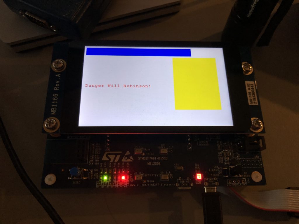
Clearly, at some point we are going to have to do a better font engine but, for now, we could build up a pretty nice UI just using primitive graphic routines (provided we get help from someone artistically inclined). Still, chances are, we are going to want to be able to display at least some bitmap graphics.
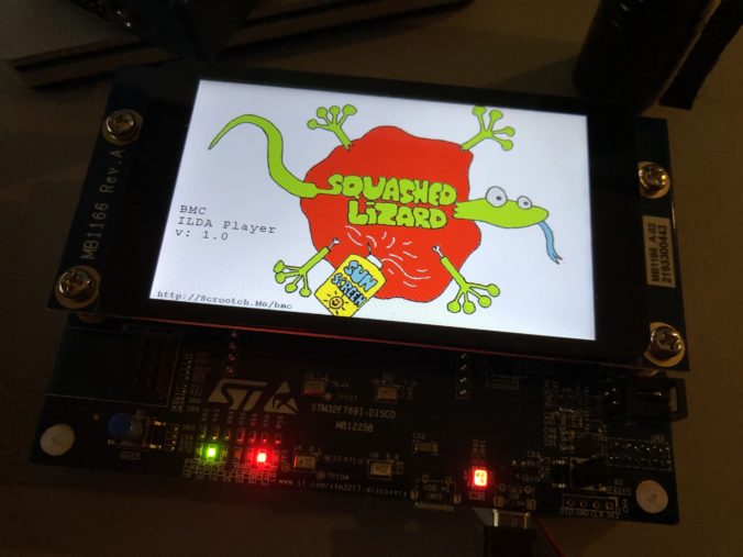
Let’s start with a splash screen. We’ve already established that I’m not very artistically inclined. But, as luck would have it, Spotify Stations played this just as I began scrambling for a bitmap to try:
And the image tickled me. A quick web search for the Aussie band turned up a higher res version of the image, so I used Photoshop to make a 800×480 16 bit (RGB565) version:

Then I used a tool we’ll revisit in another post to turn the .bmp file into C source code that can be compiled as data in flash memory and put it in a new module called UIGraphics.c:
const unsigned char uiGraphics_splash_bmp[] = { 66,77,72,184,11,0,0,0,0,0,70,0,0,0,56,0,0,0,32,3,0,0,224,1,0,0,1,0,16,0,3,0,0,0,2,184,11,0,18,11,0,0,18,11,0,0,0,0,0,0,0,0,0,0,0,248,0,0,224,
7,0,0,31,0,0,0,0,0,0,0,255,255,255,255,255,255,255,255,255,255,255,255,255,255,255,255,255,255,255,255,255,255,255,255,255,255,255,255,255,255,255,255,255,255,255,255,255,255,255,255,255,255,255,255,255,...
It is declared “const” so it will go into the MCU flash memory (read only). With the bitmap now memory accessible I next changed the drawing portion of display_Init() to this:
// Splash time!
BSP_LCD_DrawBitmap(0, 0, (uint8_t *)uiGraphics_splash_bmp);
BSP_LCD_SetTextColor(LCD_COLOR_BLACK);
BSP_LCD_DisplayStringAtLine(12, (uint8_t *)" BMC");
BSP_LCD_DisplayStringAtLine(13, (uint8_t *)" ILDA Player");
BSP_LCD_DisplayStringAtLine(14, (uint8_t *)" v: 1.0");
BSP_LCD_SetFont(&Font16);
BSP_LCD_DisplayStringAtLine(29, (uint8_t *)" http://Scrootch.Me/bmc");
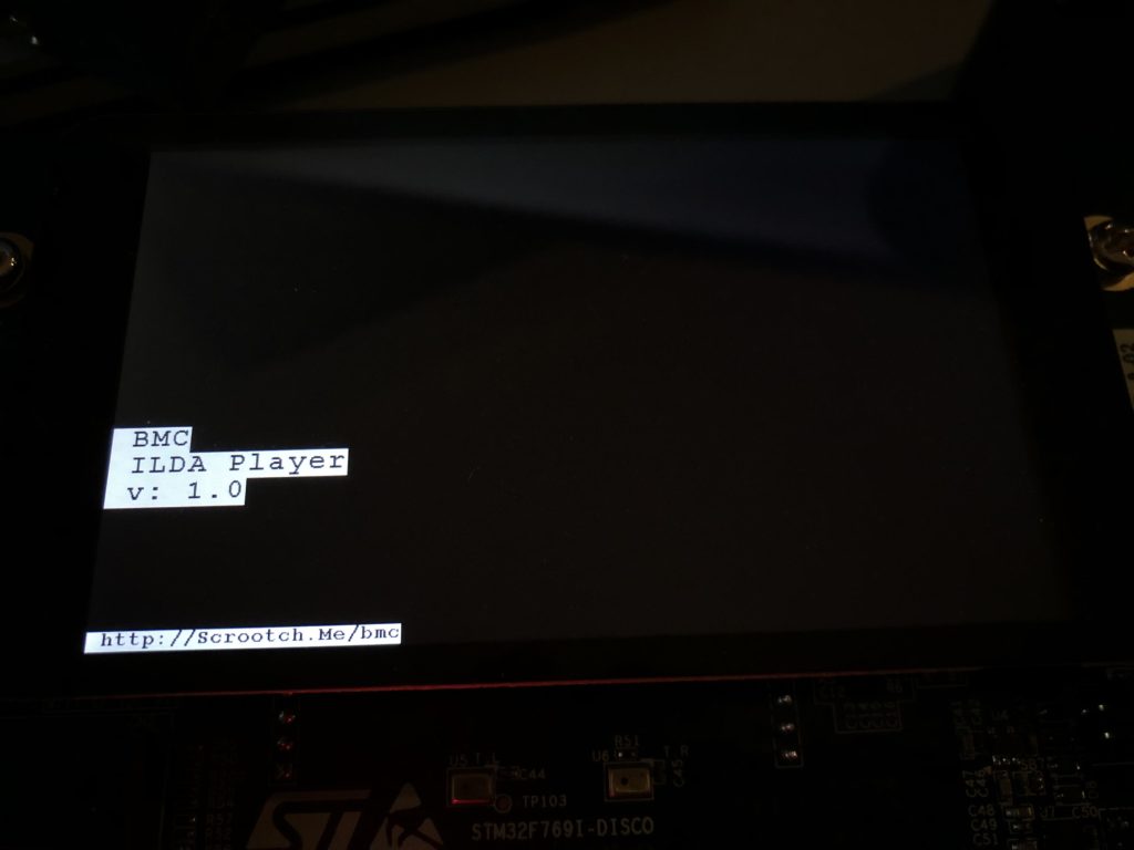
BSP_LCD_SetFont(&Font24);As you can see in the image at the top of the post, it works great, but we have another math problem looming. If we check our compiled code size, which is reported after each build, we’ll see:
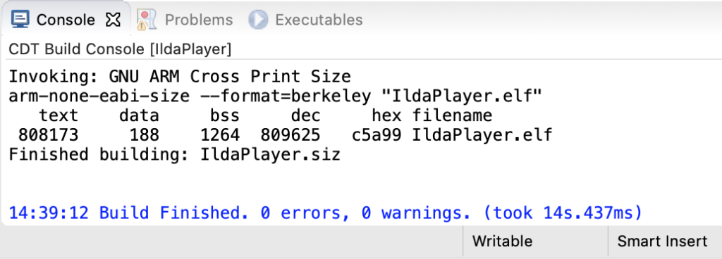
The flash part is “text” (for nerd historical reasons, ask me sometime when I’m drinking). We are pushing 800k with one image! This makes sense, 800x480x2 = 768,000. But we only have 2M (2048k) total in the MCU. There are some tricks we can (and likely eventually will) use to get this flash down. For example, we could compress the image resources and decompress them into our SDRAM at runtime when we want to use them. But still, graphics could use our on board flash up in a hurry.
As luck would have it, our eval board has 64M of external flash hooked to our MCU. The chip is a “QSPI flash memory”. Again, ST has a presentation on the QSPI interface here. But QSPI is basically an upscale from SPI, the interface we already used to communicate with a DAC. It uses 4 lines to carry data instead of 1 so it is faster. In addition, the controller on the MCU has a memory mapped mode.
This means that you can tell the MCU how to do serial QSPI read commands and it will make the QSPI memory seem like conventional memory you can access directly. ST was kind enough to include a QSPI driver for the chip on our board with the STM32 Cube samples. Once we have ported the driver to our code with the normal steps we used for the LCD driver above, we can change our uiGraphic_Init() function to this:
#include "UIGraphics.h"
#include "stm32f769i_discovery_qspi.h"

void uiGraphics_Init()
{
	BSP_QSPI_Init();
	BSP_QSPI_EnableMemoryMappedMode();
}
The QSPI flash will now ‘look’ like 64M of regular flash memory starting at and address of 0x90000000. To move our bitmap there we have to do two more things. First, we have to edit the linker file mem.ld in our project:
MEMORY
{
  /*
   * TCM 128K, SRAM1 240K, SRAM2 16K
   */
  RAM (xrw) : ORIGIN = 0x20000000, LENGTH = 512K
  CCMRAM (xrw) : ORIGIN = 0x10000000, LENGTH = 0
  FLASH (rx) : ORIGIN = 0x08000000, LENGTH = 2048K
  FLASHB1 (rx) : ORIGIN = 0x00000000, LENGTH = 0
  EXTMEMB0 (rx) : ORIGIN = 0x90000000, LENGTH = 64M
  EXTMEMB1 (rx) : ORIGIN = 0x00000000, LENGTH = 0
  EXTMEMB2 (rx) : ORIGIN = 0x00000000, LENGTH = 0
  EXTMEMB3 (rx) : ORIGIN = 0x00000000, LENGTH = 0
}
The file had for placeholders for external memory already defined. I just changed EXTMEMB0 to an origin of 0x90000000 and set a length of 64M instead of 0. Second, we have to tell the compiler where to put our bitmap data with a “section directive” in our C code:
__attribute__ ((section(".eb0text"),used))
const unsigned char uiGraphics_splash_bmp[] = { 66,77,72,184,11,0,0,0,0,0,70,0,0,0,56,0,0,0,32,3,0,0,224,1,0,0,1,0,16,0,3,0,0,0,2,184,11,0,18,11,0,0,18,11,0,0,0,0,0,0,0,0,0,0,0,248,0,0,224,
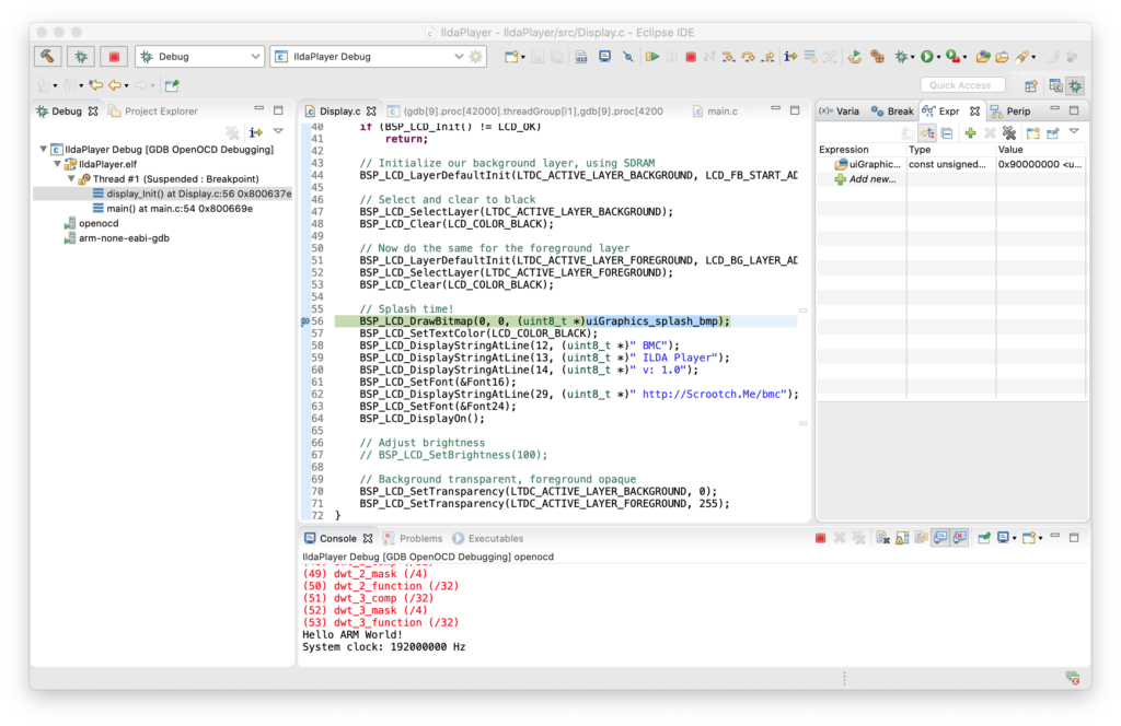
7,0,0,31,0,0,0,0,0,0,0,255,255,255,255,255,255,255,255,255,255,255,255,255,255,255,255,255,255,255,255,255,255,255,255,255,255,255,255,255,255,255,255,255,255,255,255,255,255,255,255,255,255,255,255,255,...Now if we stop with the debugger and put a watch on uiGraphics_splash_bmp (top right) we can see that the code does now expect the bitmap data to be at 0x90000000:
But when we allow the code to continue, our text still displays, but the bitmap is gone:
There is an obvious Catch-22. We have to have some code running on our MCU that properly configures the QSPI peripheral in order to write to the external flash chip. The OpenOCD setup we are using only knows how to write to the flash and ram on the MCU itself. This is why the STemWin demo did not run as expected when compiled with the IAR tools above. The IAR tool suite also didn’t know how to load graphics in external flash either and the demo relies on the same technique we are using.
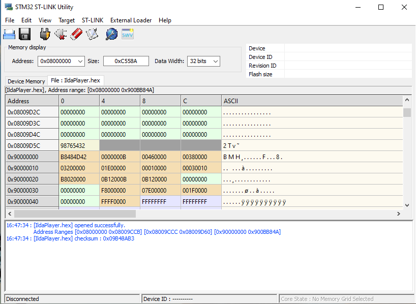
We could write our own custom loader, but we don’t have to. ST offers some free utilities for ST-Link, including this one. We can load the .hex file generated from our compile with the tool and see that our bitmap data is at the desired address:
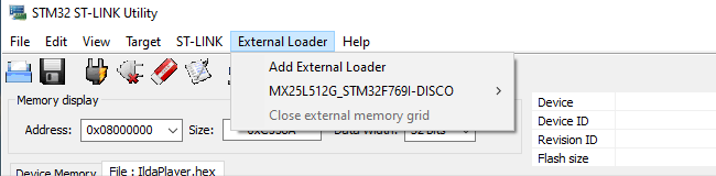
We can then use the External Loader menu to add “MX25L512G_STM32F769I-DISCO”, a flash loader ST developed just for our eval board:
Then, when we select Target / Program, the tool does all the dirty work. It puts a small loader in the MCU’s RAM, loads the QSPI flash memory with the data we want to program there using it, and programs the MCU flash normally. Cycle power and boom! Our bitmap is back, this time loaded from QSPI flash.
Note, we only need to use the tool to load the external QSPI flash chip. Once any expected resources are flashed there we can keep programming and debugging as from the Eclipse IDE as before. As always, the code above can all be pulled from the git repo.
Leave a Reply