Download OS X and Windows 32 and 64 bit versions from GitHub here.
Changes from JSE 0.1.3
Bug Fixes
- Fixed bug with frame delete not updating main editor area
- Fixed bug with frame rate warning indicators
- Fixed crash bug opening some ILDA files
New Features
- Sketch layer
- Sketch-to-ILDA point renderer with minimum path finder
- New shortcut keys and menus for tool selection and other common operations.
Notes
Well, it took an extra week, but this is the largest feature jump since the first public pre-alpha. The big news is that, although I still have some more planned features for it, the “Sketch” layer is now operational.
Just to refresh everyone’s memory, in most existing commercial laser graphic editors that I have seen, you use tools (line, polygon, etc.) to draw and those tools make ILDA points in real time based on current settings (point spacing, etc.) for the tool being used.
My idea with the sketch layer was to separate the process into two steps:
- Creating line vector art with tools
- Converting (“rendering”) the created vector art into ILDA points
The thinking was to try to maximize reuse and minimize redrawing. If the outline of a logo has too many or too few ILDA points to display correctly, you select that part of the vector art, change the properties of the shape(s), and render again instead of changing tool settings and retracing.
Similarly, you can copy and paste sketched shapes to reuse them, either in the same frame or another. Resize, rotate, adjust corners, and etc., all before committing to ILDA points at the desired spacing. But enough open mic night philosophy, let’s jump right in.
When you open the app the sketch layer, not the ILDA layer, is now the default selected layer:
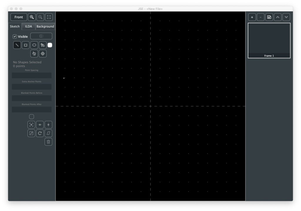
Like the ILDA and Background layers, there is a checkbox to make the layer visible/invisible. Next to that is the Render button, which we will come back to once we have something drawn. Immediately below the Render button are 4 tool buttons and a color selector to create shapes in different colors.
We’ll start with the line tool, which is selected by default. Just point to a spot in the main edit area and click. This will create a new shape with one “anchor”. Move the mouse and click again. There will now be a line between two anchors. You can just keep clicking to extend the straight line shape. The behavior is very similar to the point tool on the ILDA layer covered in the JSE 0.1.1 release notes.
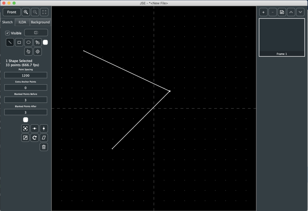
A rubber band shows the potential line from the last placed anchor. If you hold the <shift> key the angle of the next segment will be constrained to the nearest 45 degrees (0, 45, 90, etc.) If you hold the <ctrl> key the end of the rubber band will ‘snap’ to an existing anchor if one is close by.
When you are done with a line, hit the <esc> key and you are ready to start another line based shape somewhere else.
The next two tools are “Rectangle” and “Ellipse”. The use of both is very similar. Click and drag (hold the mouse button down) in the main edit area. A thin grey outline will show the shape. When you release the left mouse button the shape will be created.
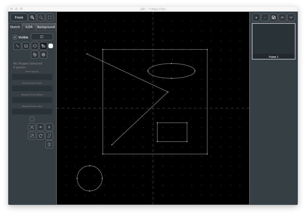
If you hold <shift> with either tool, width and height will be locked together so you can draw squares and circles.
The Pen Tool is a simplified implementation of the pen tool in Adobe Illustrator. If you just click, it will work like the line tool. But if you click and drag when placing an anchor, you can make the connection to the previous anchor curved:

Like Illustrator, the assumption is for the line to leave a curved anchor in a complimentary curve. And, also like illustrator, you can straighten the anchor ‘exit’ (leave the anchor using a straight line) by pointing at the anchor right after you create it and clicking again (or by selecting “Straighten Anchor Exit” from the Edit Menu).
Like the line tool, you can <shift> and <ctrl> to either constrain the pen tool to 45 degree angles or snap to an existing anchor.
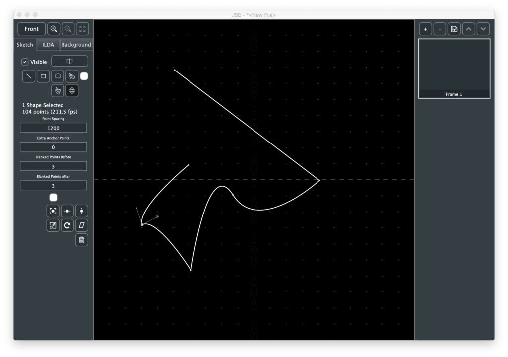
Below the shape creation tools are two more tools. The first, a hand, is the Select Tool. With it you can select one or more complete shapes, a specific anchor on the the shape, or the curve controls for a curved anchor:
Like the ILDA layer, whatever is selected can be moved with the arrow keys (hold <shift> for smaller steps) or deleted with the <backspace> key.
You can also move things with the mouse using the Move Tool next to the Select Tool. Like the select tool, what you are about to select is highlighted, but you can then click and drag to select and move an object with one operation.
If you click and drag in blank space (nothing highlighted under the mouse cursor), any already selected items will be moved. This can be handy for any curve control handles that may be off screen.
First select the anchor, by clicking on it with either the Select or Move Tool. Then select the desired curve control (entry or exit) for that anchor using either the Edit Menu or the shortcut keys shown in the menu (<;> for entry, <‘> for exit). Once the control is selected you can then move it by clicking and dragging in blank space with the move tool.
If you are moving an anchor, holding the <ctrl> key will let you ‘snap’ it to an another anchor’s location.
If you play with the select and move tools you will quickly realize that the shape creation tools don’t really create different things. They all create anchors which are connected to each other with “Cubic Bézier Curves“.
This lets you mix and match tools. For example, start by drawing a simple shape with the line tool:
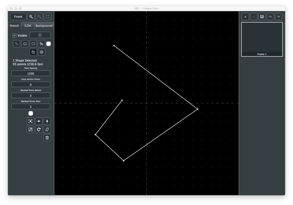
To add anchors to this shape later we select an existing anchor with the Select Tool. The Line Tool will then show a rubber band to the mouse from the selected anchor and then back to the next anchor (if any):
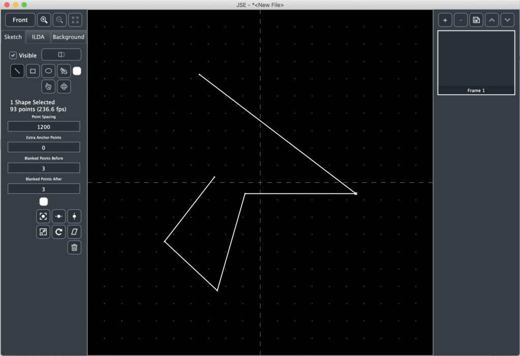
We could click to add additional anchors, but let’s say we want the new segment curved. Hitting <p> will switch from the Line Tool to the Pen Tool. We can then insert curved anchors into our previously straight lined shape:
Of course, we could have selected the Pen Tool using the button or the Edit Menu, but the shortcut key let’s you do it without moving the mouse, which can be handy if you are tracing a loaded background image, etc. See the Edit Menu for a list of all the available tool shortcuts.
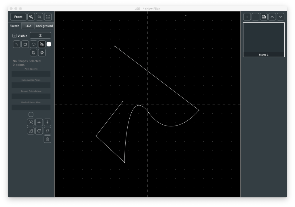
You can go back and forth between curved and straight for existing anchors as well. Just select the anchor and pick “Straighten Anchor” or “Curve Anchor” from the Edit Menu. Once an anchor is curved, you can adjust the control handles to get the shape you want:
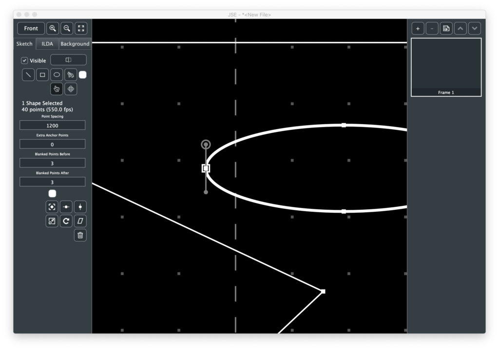
When one or more shapes are selected, some info is populated and displayed below the tool selection buttons. The four edit boxes control how the shape(s) will be rendered. Point Spacing controls the average gap between generated points.
Don’t panic that the default value seems so large (1200). JSE is a 16 bit editor. It exposes all the resolution available in an ILDA file. Many commercial editors expose lower resolution. You can tell this by checking the available XY coordinates. If a system goes +/- 8,000 instead of +/- 32,000, it is creating 14 bit images and a point spacing of 300 would be equivalent.
Extra Anchor Points is just as its name implies. It will add extra points at each anchor location. This is for things like making the corners of a rectangle brighter and sharper.
The last two fields control how many blanked points are placed at the first and last anchor points before and after a shape is scanned.
Below the edit boxes is another color selector. This let’s you change the color of shapes after they are drawn.
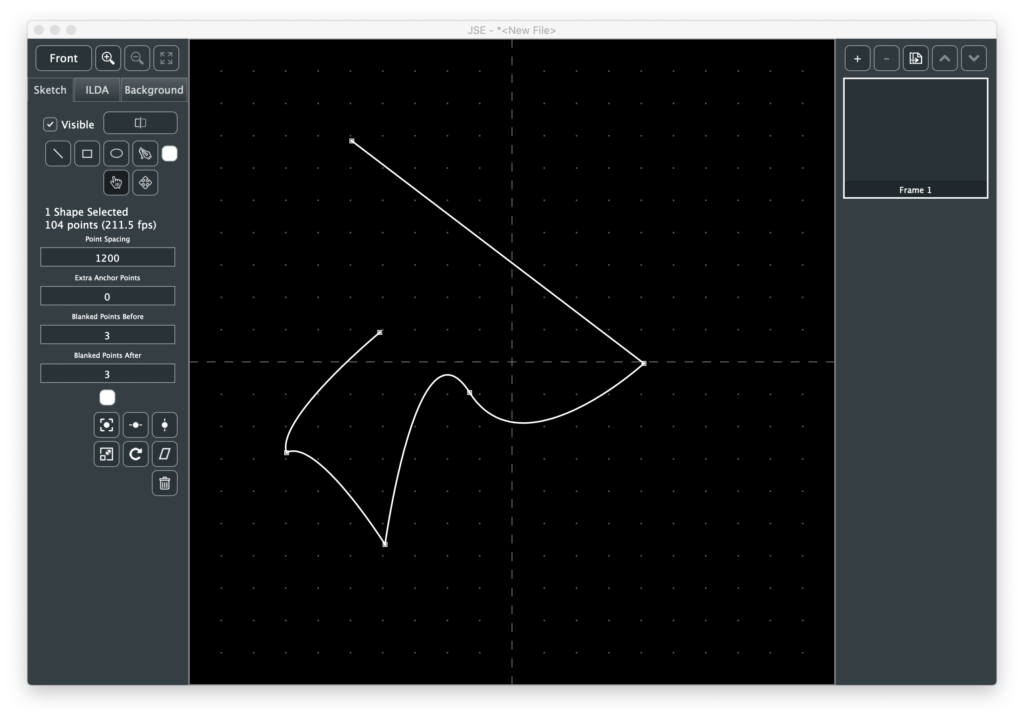
Next are some simple transforms that can be applied to selected shapes. To get a feel for those let’s first select our new curvy steam punk hatchet head. Note, we want to select the whole shape, not just one anchor:
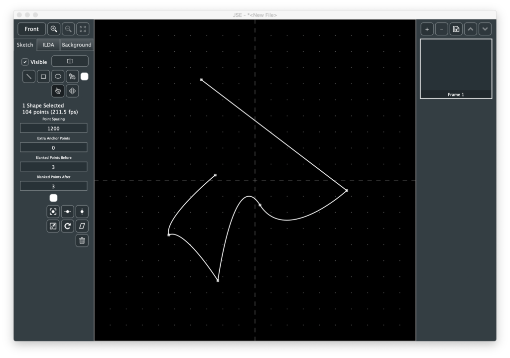
The first three transform buttons are just for centering, on the X axis, the Y axis, or both:
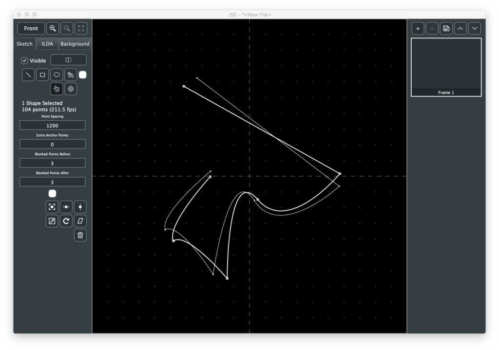
Before using the other transforms, let’s copy and paste our selected shape using Copy and Paste from the Edit Menu, or the <cmd/ctrl> + C and <cmd/ctrl> + V shortcuts.
At first, it might seem that nothing has happened, because the paste put the copy at exactly the sample place, but it also selected the pasted shape(s). So we can move the copy with the arrow keys or transform with, say, the Rotate button:
In addition to Rotate you can Scale (bigger, smaller, or invert) and Shear/Skew selected shapes. Like the ILDA layer, transforms can either be based on the center of the edit field or the center of the selected shape(s).
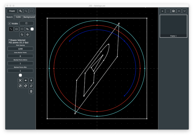
Now that we have some shapes, let’s use the Render button. Because it will be getting more options, the button invokes a popup:
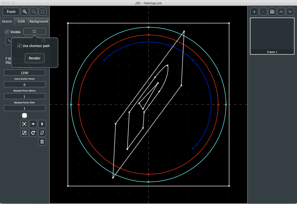
In this version, the only available option is “Use shortest path”, which is on by default. To better understand this option, let’s click on the Render button, then hide the Sketch layer and look at the ILDA result:
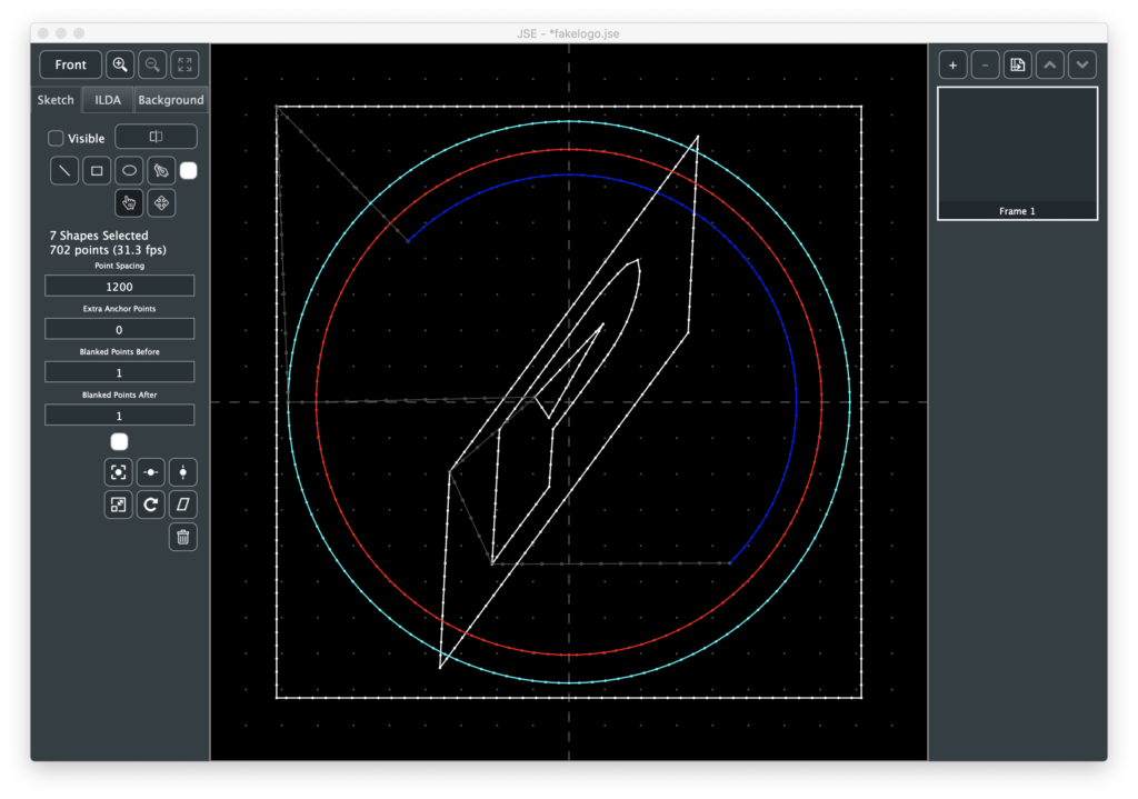
To be an ILDA scan, we need to do more than just convert each shape into points. We need to connect all the shapes together with invisible lines and form a loop. This is a variant of what is called the “Traveling Salesman Problem” (TSP). Basically, how to visit everywhere you need to go while traveling the shortest total distance. It is one of the classic, surprisingly difficult nerdvanna-type computer science problems, with graduate students striving to make even minuscule improvements in computation time.
In our simple case, one of the classic approximations, “Nearest Neighbor”. combined with “Arbitrary Start Node” works well. Basically, after each shape ends, the closest start or end of another shape is found. This repeats until there are no more shapes. The total connecting distance, including the return to the first shape, is tabulated. The program tries this starting at the beginning and end of each shape, and then uses the combination with the lowest connecting length.
Most the time, this works quite well. But there are cases where you want points in a very specific order (ex. a signature you want to trace out). In those cases you can turn off the Shortest Path option and the shapes will be scanned in the order and direction you created them:
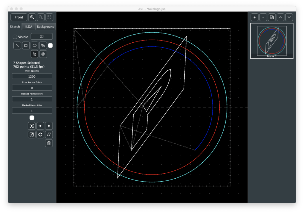
This will almost always result in more total points in the ILDA image, but gives you complete control over order.
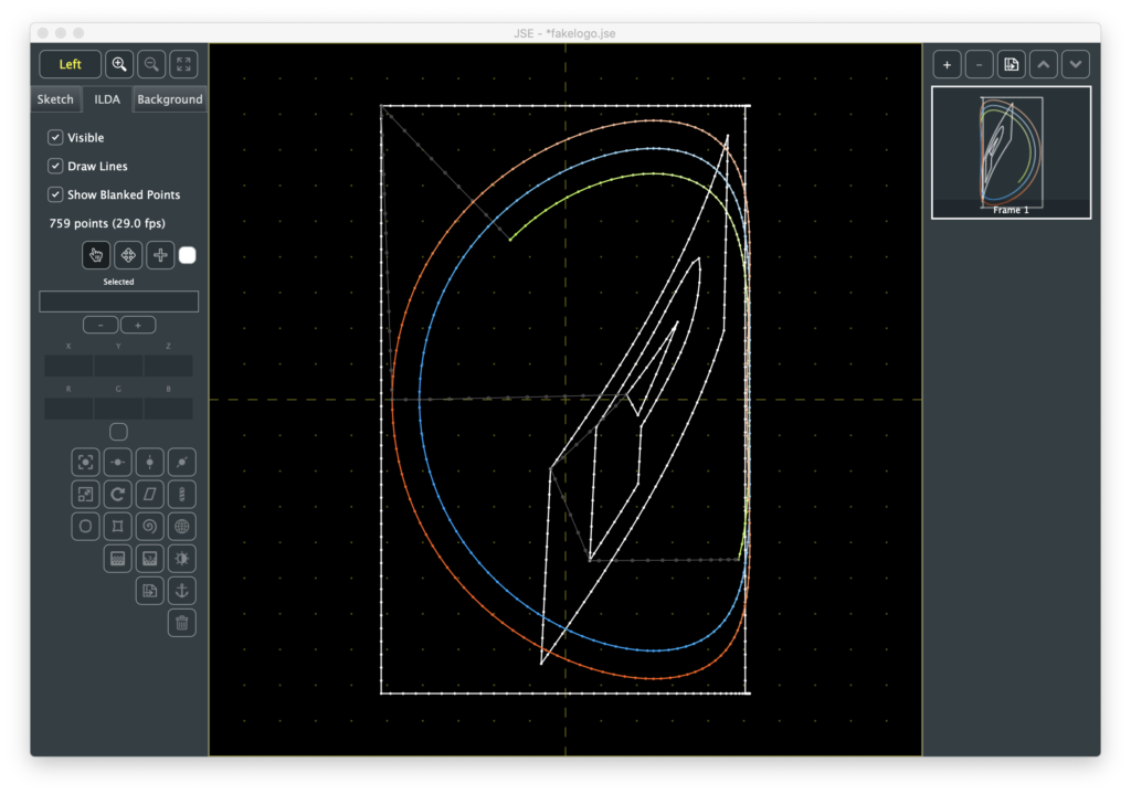
Regardless, if you don’t like the point spacing, etc. of a given shape you can adjust that shape’s parameters and render again. Once you are happy with the Render output, you can hide the sketch layer and use the ILDA layer to tweak or add specific points, apply color effects, 3D Transforms, etc.
Still lots to come, but hopefully it is starting to feel more like a real content creation tool.
Leave a Reply