Built Mac and Windows versions can be downloaded from GitHub.
This week we’ll take a break from my normal drivel about how the different pieces of BMC are being developed and cover a public release, pre-alpha , of my simple ILDA editor.
For those jumping in cold, ILDA is an industry association for laser entertainment. When I refer to ILDA here I am talking about the association’s standard for exchanging laser graphic information. Although the standard dates back to the 1980’s, the projection technology still hasn’t really outgrown it. As I explained early on, it is basically a game of ‘connect-the-dots’, with the laser beam quickly tracing a pattern. It’s a bit like a fast Etch-a-Sketch, but the laser at least can be hidden, or ‘blanked’ for part of the trace.
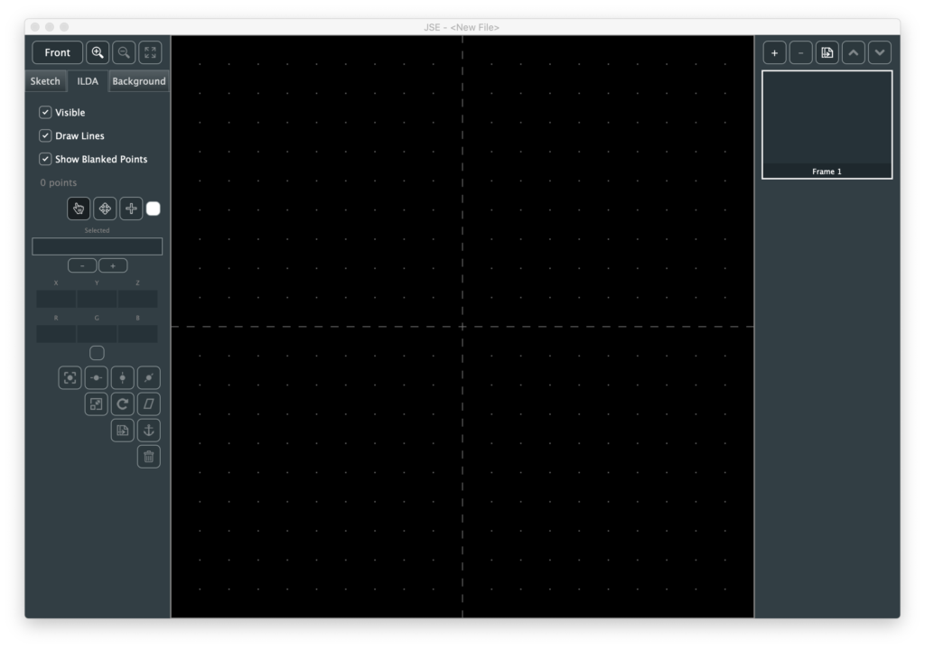
Warning! This is pre-alpha software! That means it is far from full featured and has not been extensively tested. Please use with care. Particularly when it comes to playing any generated ILDA content on scanners. That said, let’s cover what is working. When you start JSE on either Windows or Mac you get a default file with 1 frame, and no points:
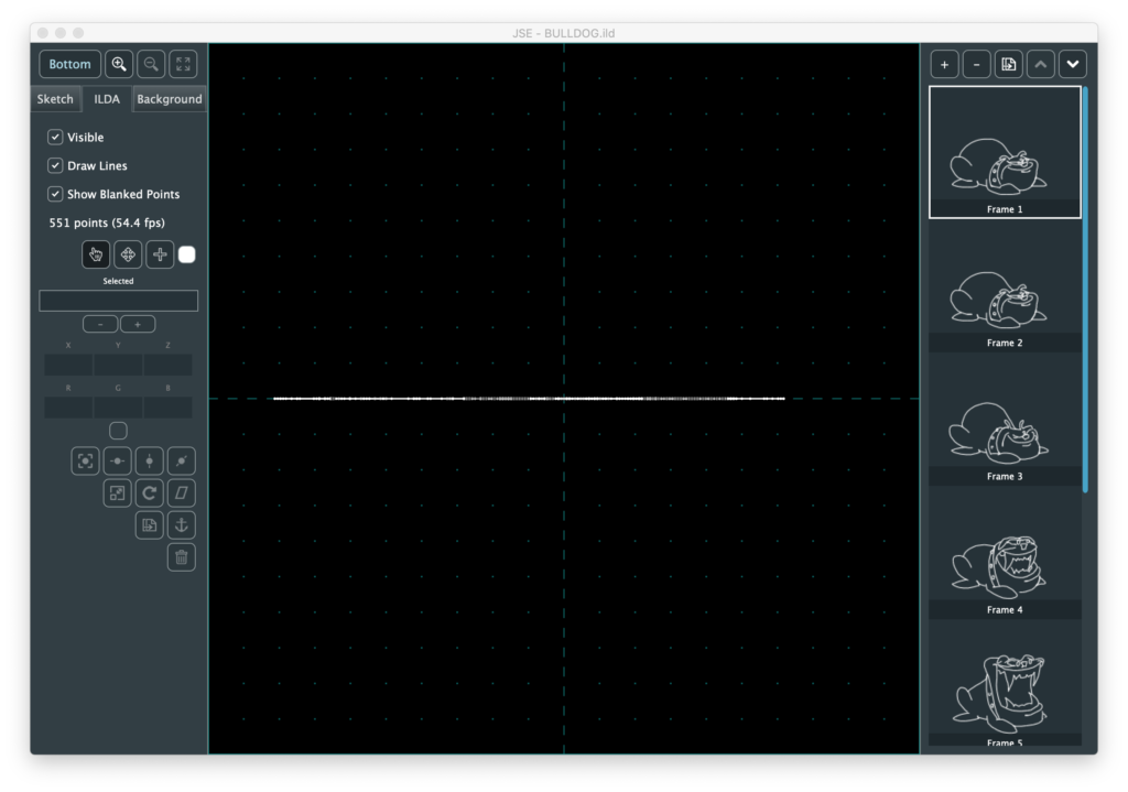
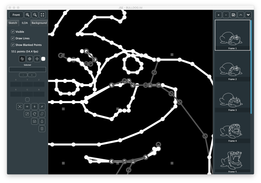
For those who have been following development, I did move a few things around and hide some under-construction areas for the release. To more quickly cover what is working, let’s open an existing .ild file to start. I’m using this one, created by the now defunct LaserMedia sometime in the late 1980s. Unfortunately I do not have the name of the original artist to credit. After selecting the File / Open menu and browsing to our file we should have this:
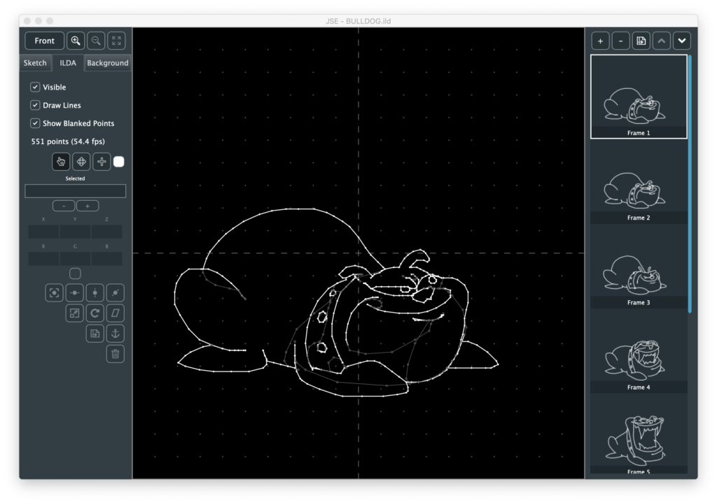
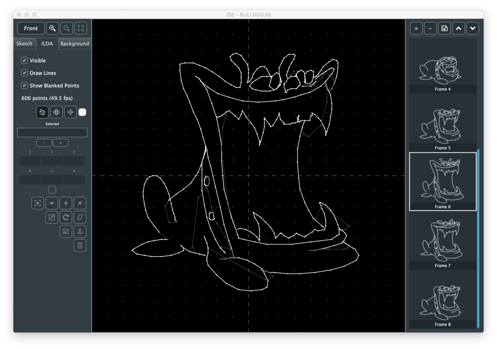
A nice little 8 frame animation of a bull dog ‘chomping’. The right edge is our frame management. The highlighted frame is the one we are editing. If we want to edit the ‘maximum chomp’ frame (#6), we just scroll down and click on it:
Note, I’ve tried to support modern pads and gestures wherever I can. You don’t actually have to click and drag the blue scroll bar, you can point at the list and either use the mouse scroll wheel, or the two finger scroll gesture on your touch pad.
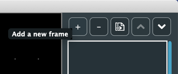
The buttons above the list are for frame management. From left to right, they are:
- Insert a new frame after the currently selected one
- Delete the currently selected frame
- Duplicate the currently selected frame
- Move the currently selected frame up in the frame order
- Move the currently selected frame down in the frame order
Since my icon graphics skills are utter crap, it might not always be clear what a button or control does. No worries, just hover the mouse over it and some tip text should appear:
Moving over to the left side, the buttons on top here are for view control:
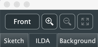
The top left button is for toggling viewing angle. ILDA is 3D format. That means that in addition to X (horizontal) and Y (vertical) information, each dot, or point, can have depth information. To see and edit that information we have to have different points of view. I’ll be adding more sophisticated 3D view support later, but for now clicking this button will toggle between three views:
- Front
- Bottom
- Left
Yeah, I know, seems weird to use these three, but the ILDA spec calls out Z like this:
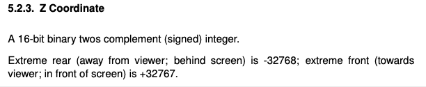
It’s a subtle thing, but the ILDA Z coordinates follow a different ‘thumb rule’ than ILDA X and Y. Since I don’t have good 3D view control and indicators yet, I picked the three views where up and right on our graph are always positive values and down and left are always negative values. YMMV but I found it too disorienting to have the polarity of things switch without more visual feedback. Anyway, the old graphic I’m using has no depth for any of the coordinates (all set to 0), so Bottom and Left are just lines of dots on one axis or the other:
But other graphics, like this waving Canadian flag I found online, are more interesting:
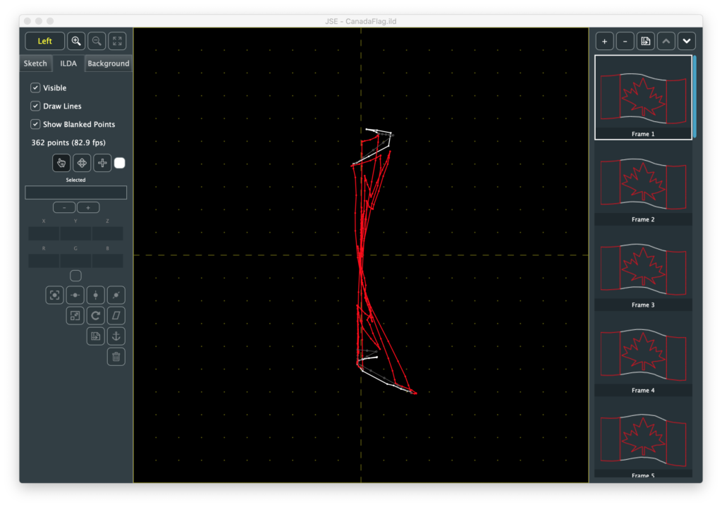
Going back to our front view, the next 3 buttons are zoom in, zoom out, and Fit All. Zooming and panning is something ILDA editing involves a lot, so these buttons are just one of multiple ways to do it:
Keyboard Zoom/Pan
You can hold the <cmd>(Mac)/<ctrl>(Windows) button and press ‘+’, ‘-‘, or the arrows keys to zoom and pan.
Scroll Wheel Zoom/Pan
Scroll alone pans up and down. Hold <shift> to pan left and right. Hold <ctrl> to zoom in and out.
Touch Pad Zoom/Pan
Use two fingers to pan, pinch and spread to zoom.
However you do it, be forewarned that the bulldog’s face will haunt your dreams:
If you get zoomed in and lost, the Fit All button, or <cmd>(Mac)/<ctrl>(Windows> + ‘0’ will get you back to where we started.
The three tab button below the view controls select which layer we are working on. The Sketch layer currently does nothing (but will do quite a lot soon, I promise!).
The Background Layer controls the visible grid and allows you to add a reference image to edit against. We’ll come back to it later.
The ILDA Layer is the ILDA coordinate data, which we already have loaded, so let’s explore this layer first. The top section is, again, view control:
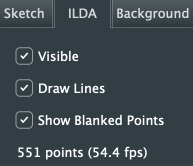
- “Visible” controls the visibility of the whole layer
- “Draw Lines” turns the connecting lines between points on and off
- “Show Blanked Points” hides and reveals the parts of the image trace that are ‘blanked’ or invisible
Note: When blanked points are hidden they cannot be selected for editing, either with the different edit tools or the Select All menu option.
Below the three check boxes is a text indicator showing how many points are in the currently selected frame and what it’s frame rate would be at the current scan speed (fixed at 30 kHz in this release).
Next are our three primary tools and our our selected points display:
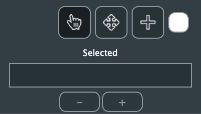
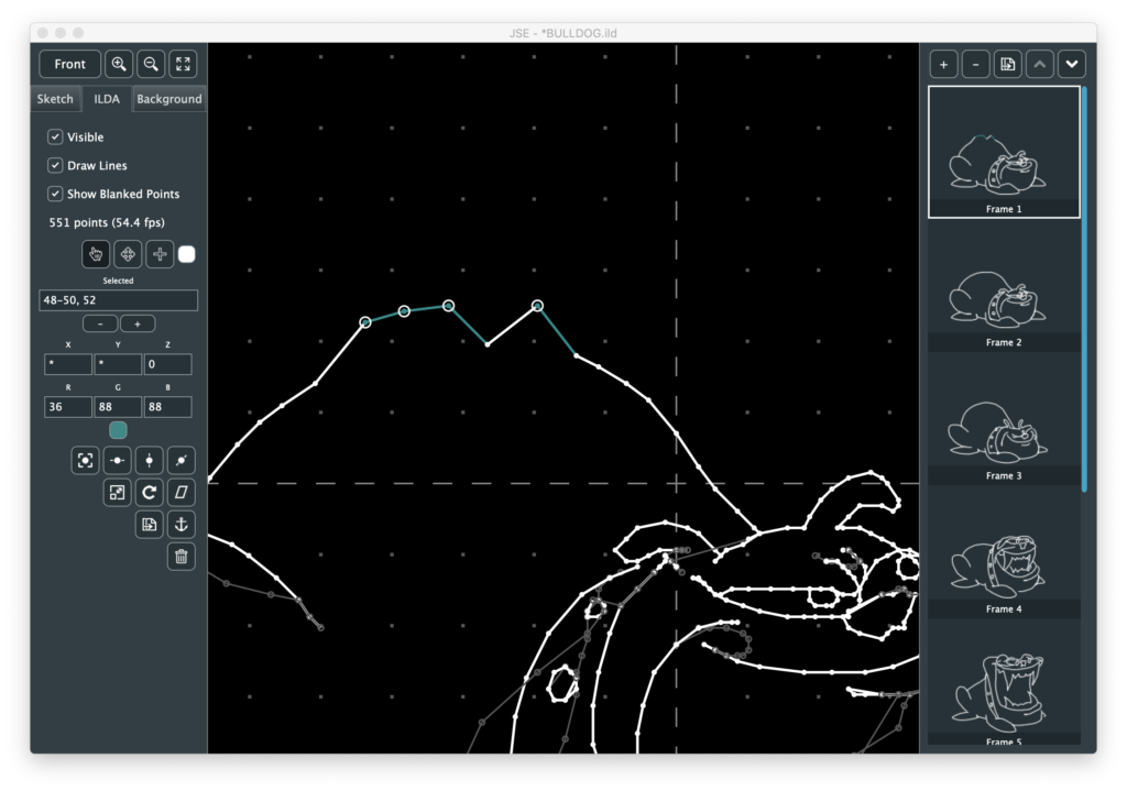
The hand is a ‘Selection Tool’, and is active by default. It is, as its name implies, meant to select points for manipulation. When it is active moving the mouse over a point on the screen will cause a circle to be drawn around it:
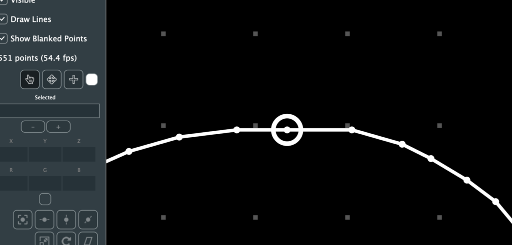
If you click the mouse the point will have a smaller circle fixed around it and the “Selected” field will show the point number:
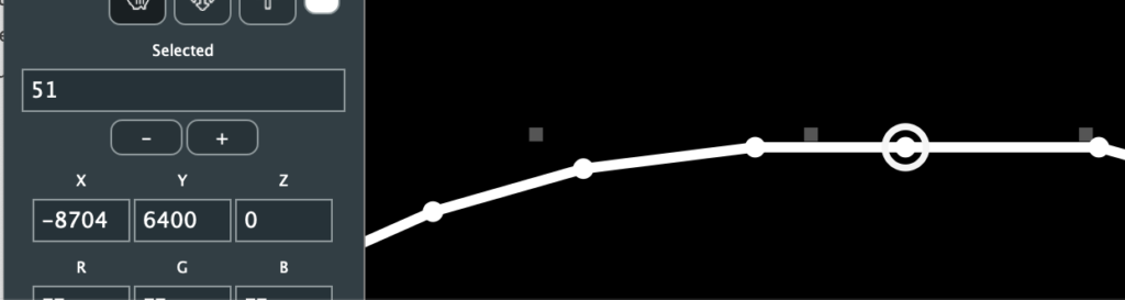
A bunch of other stuff filled out and activated, but we’ll get to that in a moment. We can directly enter points to select as numbers in the selected field, and we can increment and decrement our selection with the – and + buttons below it (or the ‘[‘ and ‘]’ keys as a shortcut). This can be more useful than it sounds when you are exploring someone else’s ILDA file. For example, putting in ‘1’ to find the first point, then using the buttons or shortcut keys to see what order the image is traced out in.
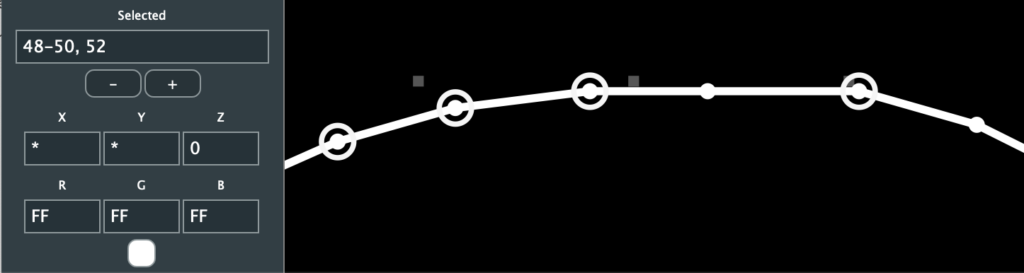
The select tool can also select by clicking and dragging a rectangle around points. Holding down the <cmd>(Mac)/<ctrl>(Windows) lets you add to or toggle selections. Holding down the <alt> key lets you subtract from a selection:
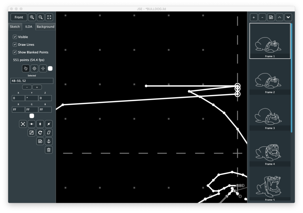
The X, Y, Z, R, G, and B fields show the raw ILDA data for the selected point(s). You can edit a point with these fields, but it generally isn’t very useful. For example, in the case above, if I edit X to 0, all the points selected will jump to zero:
Likewise, it isn’t particularly convenient to convert colors into hex values in your head. An easier way to adjust color is to click on the small color swatch below the RGB values and use the popup color selector:
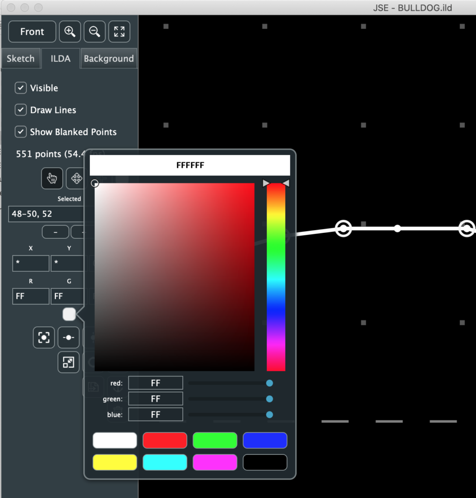
If you have a web color in mind you can type it in at the top. The hue and color boxes let you pick a color with the mouse. Slider bars are also available for direct control of R, G, and B. And there are color swatches at the bottom.
Note: Laser colors are a lot of work to fine tune, so the swatches are the RGB ‘all in colors’, plus black for blanking. You can dismiss the popup by clicking on the color swatch again, or any inactive part of the window.
To move our freshly colored points we can use the arrow keys on the keyboard.
The arrow keys alone move the points in fairly big steps. Holding the <shift> key makes the relative moves smaller/finer. Another way to move a selection is with the “Move” tool, next to the select tool.
If points are already selected, activate the move tool and then click and drag on the editor area. The selected points will move.
When you point the move tool at a single point, it will highlight and you can click and drag that point with one operation. This is meant for point by point cleanup once an image is sketched out.
However you move points, it is important to remember that you are moving relative to your currently selected viewing angle. If that is “Front”, your move will be X and Y. If one of the other views is selected, one direction of the move will be Z, or depth.
Below the color swatch are a number of operations you can perform on selected points (with more to come!):
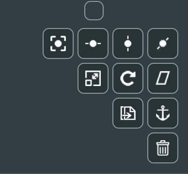
The top 7 are pretty self explanatory. I’d suggest just trying Edit / Select All to pick all the points and play with them. The one thing worth mentioning is that the transforms, scaling, rotation, and skew, all have an option to control how they are centered. You can be centered on the selection:
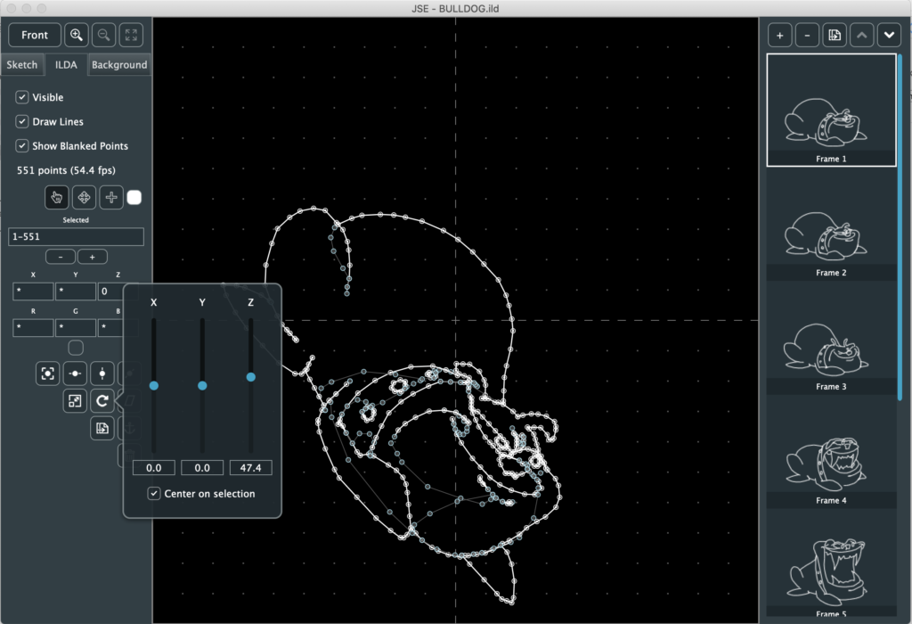
This means the operation (in this case a Z rotation) is around the center of the selected points themselves. If you turn the check box off, the operation will be centered at 0,0, or the cross hair in the middle of the editing area:
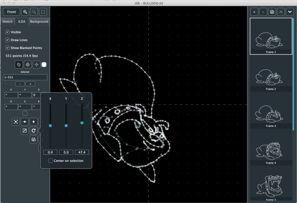
Don’t let the explanation above confuse you. This is easy to understand if you rotate something off center, like the dog on the Z axis with each option and watch for yourself.
The next two selection operations are more laser-image specific. Duplicate creates and inserts an identical point right after the selected one. This is useful if you want to make hot spots in your images, like corners on a cube or beam dots.
The ‘Anchor’ button (yes, that’s what it is supposed to be) is similar. It puts a blanked (invisible) point before the selected one(s), at the same location. This is useful if you are getting scanner movement artifacts at a laser off->on transition when your graphic is projected.
The trash can, of course, deletes the selected points. You can also delete with <delete> or <backspace>.
This leaves the Point Insertion Tool next to the move tool. It was actually created for modifying existing ILDA frames, but while the Sketch layer is under construction, let’s create a simple animation with it.
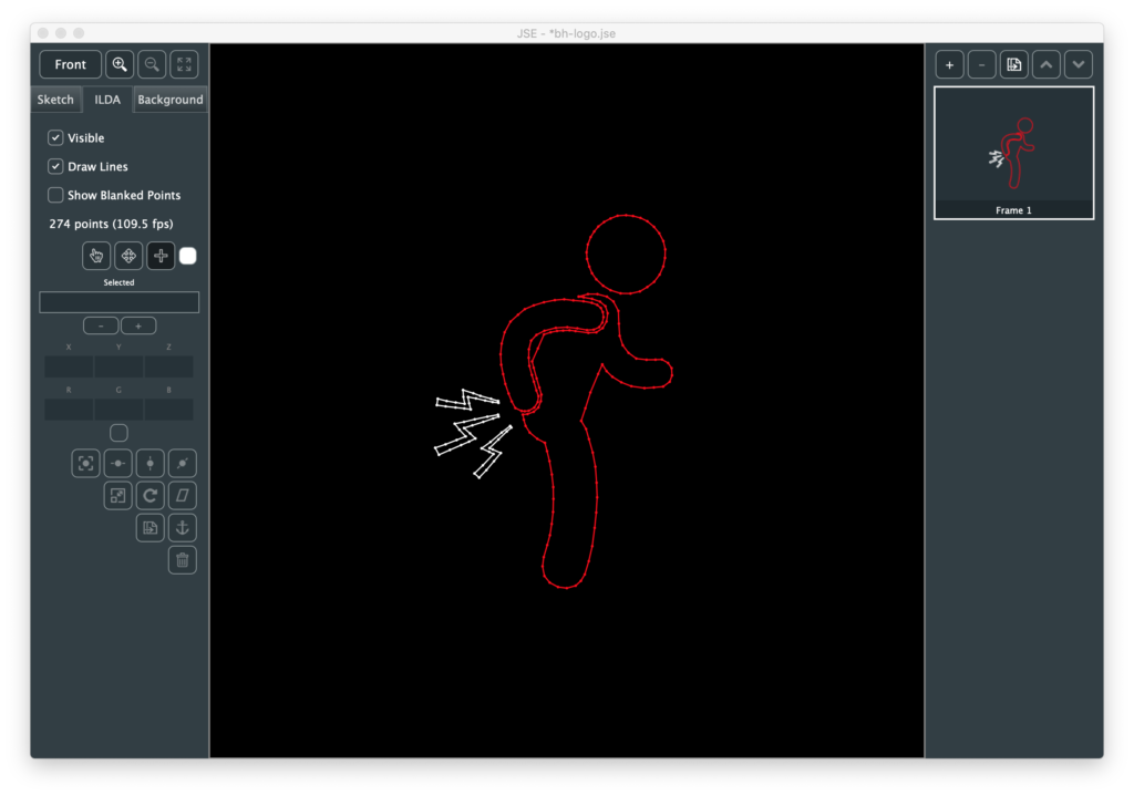
First, File / New to get us back to a blank canvas. Make sure that the “Front” view is selected:
I am going to want to trace against an existing image, so I next select the “Background” tab and click the “Select Image” button. The first simple image I found was this one:
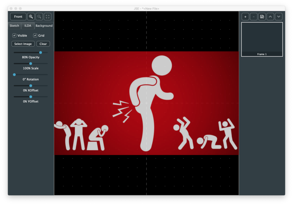
Alas, I have no idea who created this fabulous international symbol for butthurt. I tried images.google.com for a reverse search to no avail. But it is perfect for our purposes. I like to see the grid, so I turned the opacity of the image down a bit. Normally, you want to use as much of the ILDA area as you can, so there are also scale, position, and rotation options, but I’m just doing something down and dirty, so I’ll stop here.
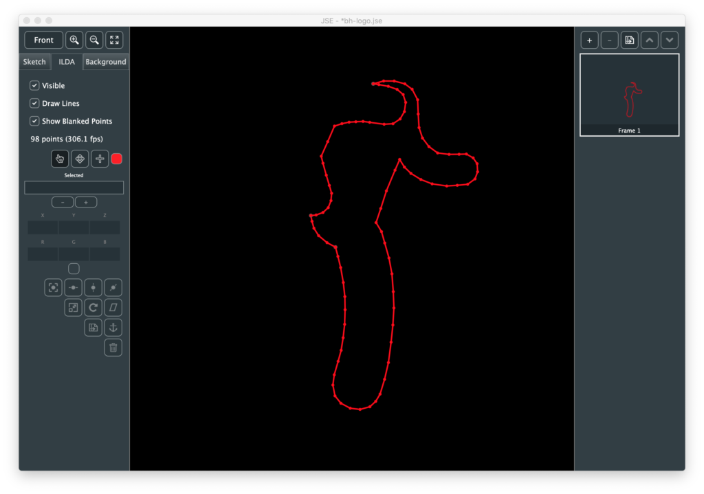
Next I go back to the ILDA layer, zoom in a bit, select the “Point Insertion Tool”, and use the color swatch next to it to select red. Now I am dragging a red dot around the screen (under a cross hair cursor you can’t see in the screenshot):
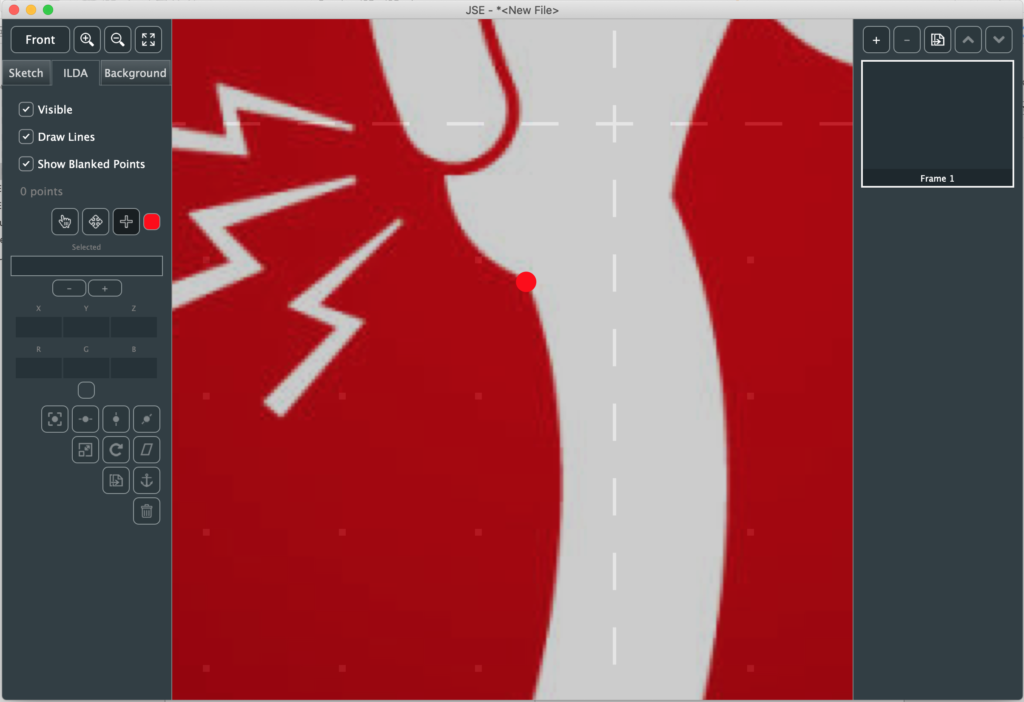
I put the dot at an indiscrete spot over the image and just start clicking along the outline of the body:
As I click to add each point, it becomes the currently selected, so I can tweak its position in small steps with <shift> + the arrow keys.
If I get to a sharp turn and know I want to put extra points at that position, I can hold the <ctrl> key and the dot will snap to an existing point if it is near one.
Although it isn’t useful here, you can also hold the shift key and the dot will snap to the nearest 45 degree angle (0, 45, 90, etc.) from the last point.
I tend to use the mouse and scroll wheel to zoom and pan as I go (yes, I’m thinking about an auto pan feature), but you can adjust the view however you like (dragging the dot off to the edge of the edit field to use the menu or a tool bar button looks weird, but won’t hurt anything).
As I finish outlining the body, I <ctrl> click to snap to the starting point and hit <ESC> (which deselects all points):
I’ve turned the Background Layer off to make it easier to see. Now I need to decide where to break off and draw other items, for example, the head.
I could go over and use the color selector by the Point Insertion Tool to select black to make the invisible line, but instead I used the shortcut ‘B’, which toggles between blanked and the last non blanked color. Similarly, ‘C’ rotates between the 7 non blanked standard swatch colors (these shortcuts are shown in the Edit menu when this tool is selected if you forget).
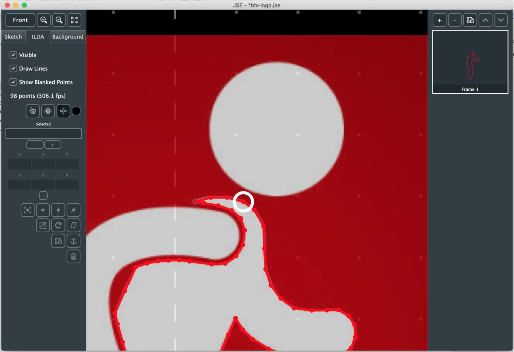
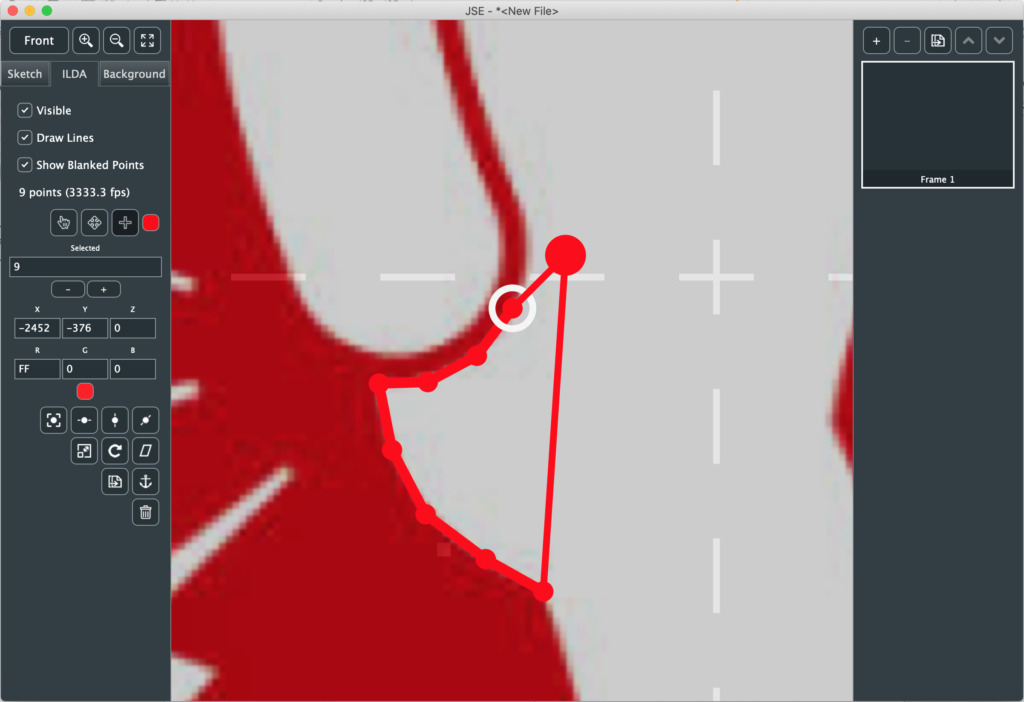
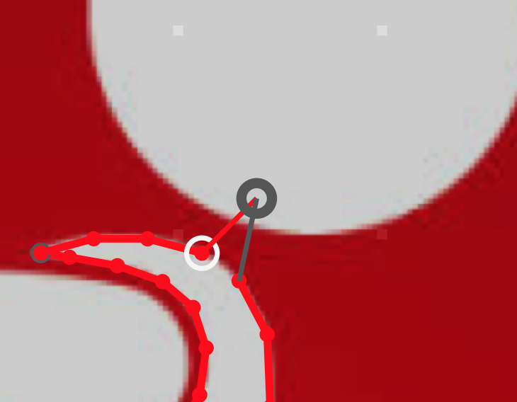
Still using the point insertion tool, the highlight circle above shows me the point I am going to insert immediately after if I click. Once I click I get a dot and can place it wherever I want:
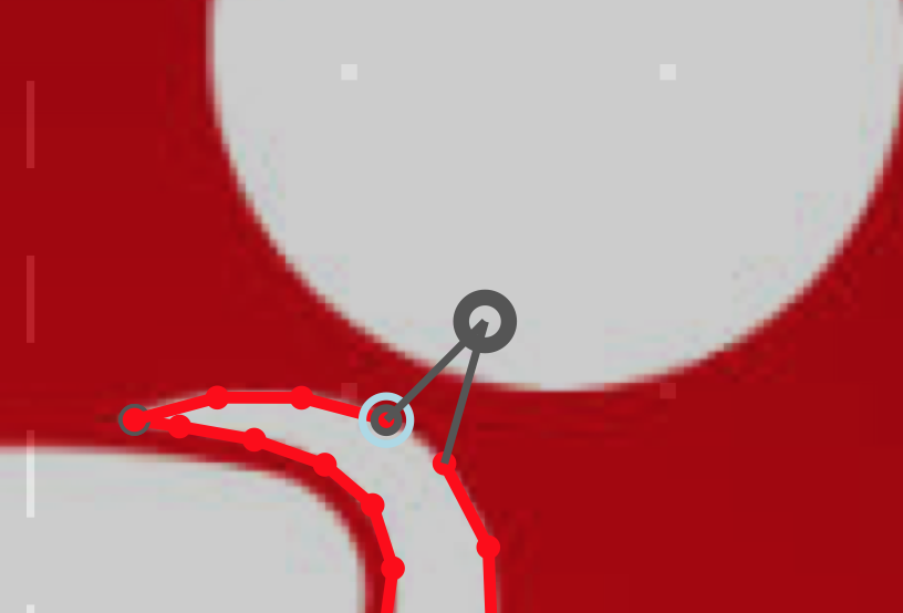
However, in a case like this, trying to make an invisible line from one section to the next, the first thing we are usually going to do is hold <ctrl> and put a point in the new color (in this case blanked) at the point we just selected, so there is a shortcut. Holding <alt> while you click will do that first step for you. That is, you auto inserted a point where you highlighted and the dot represents your second point in the new color:
If you drop a point by mistake you can always delete it with <del> or <backspace>, or use the Undo feature (<cmd>(Mac)/<ctrl>(Windows) + ‘z’). I rushed a bit and ended up with this:
Normally this is where you might turn on the laser output and use the move, duplicate, anchor, etc. features to clean the image up, but I haven’t written that yet, so I just adjusted a few points by eye.
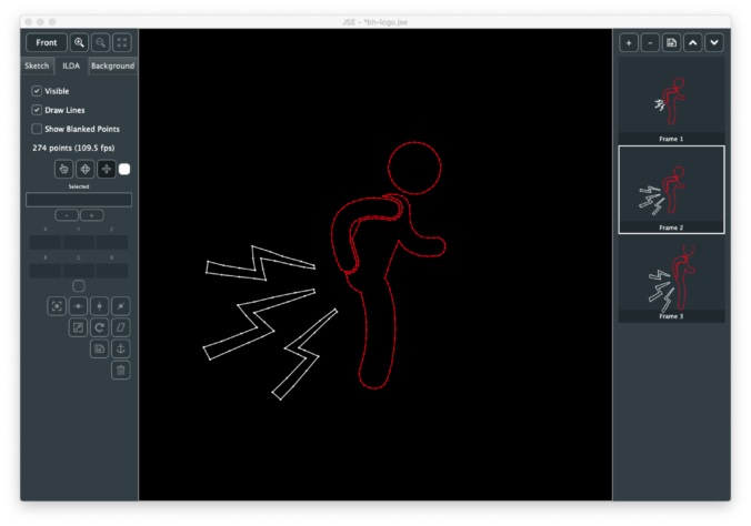
Next I duplicated the frame, turned “show blanked points” off, selected the lightning bolts, and scaled and positioned them:
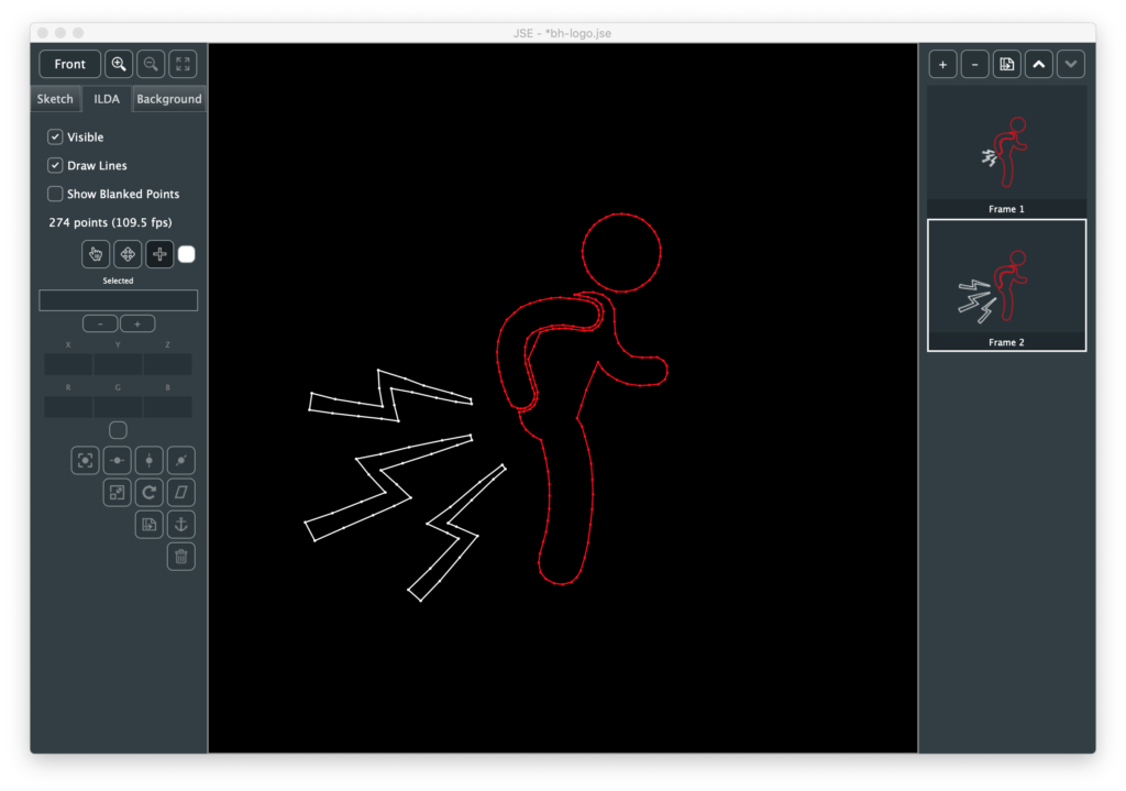
Last, I made blanking visible again and moved those points a bit and dropped a few additional points on the larger lighting bolts.
We can save the file to a .jse file (our own format that includes meta data, like the background image). Or we can use File / Export ILDA File to generate a .ild file.
Honestly, my expectations were pretty low. Whenever I’ve made something for lasers in the past I’ve spent a lot of time tweaking and editing points, but scanners have gotten a better and this is all pretty simple shapes. I wish I was better at photographing lasers:
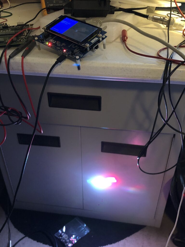
Because this turned out a lot funnier than I expected. I’m thinking about projecting it on the side of my house for the rest of 2020, tbh:
Maybe animate the lighting bolts in color… Anyway, no, JSE isn’t a proper creation tool yet, but this is just the first Alpha! I promise, more good things to come soon. And, rest assured, your comments, suggestions, even angry tirades about anatomically impossible sex acts I should conduct with a diode laser because my editor is so stupid, are all appreciated!
Leave a Reply