For anyone bothering to read this drivel, we knew after this test that we could freeze the rolling shutter effect as Marty Canavan from YLS Entertainment requested.
But Marty doesn’t want to use the effect for a single video shot, where everything can be dialed in manually just prior to each video take. He wants the ability to use the effect multiple ways in one continuous video take. Effectively a live performance. So we need a way to sync our system to the video.
Conceptually this is pretty simple, we want to set everything up, then gate our scan timer off of the camera’s vertical sync (when the camera is about to scan the next frame). We don’t need to do this continuously, just once to kick off each effect.
Vertical sync is a concept that dates back to the earliest forms of television:

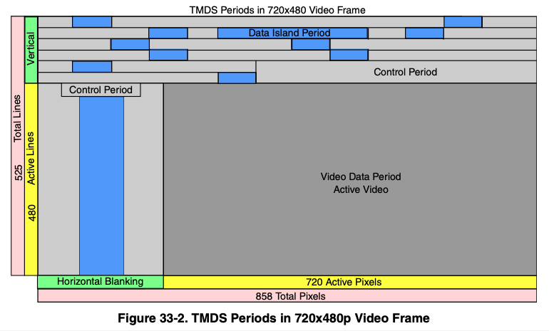
The picture lines were scanned one at a time, top to bottom, and ‘vertical sync’ is the time interval when the scan has to be deflected back from bottom right to top left. The technology has changed dramatically, but the basic need, synchronize with the start of the next frame, has never gone away although gamers tend to think of it as the choice between frame rate and tears in the photorealistic urinals in their game:

Back in the dark ages I worked on first generation video conferencing equipment and early consumer digital cameras as part of Canon’s Advanced Digital Imaging group, so these concepts aren’t new to me. But I haven’t really paid close attention to the technology since, so my first step in this process was to look at the side of the camera, read “HDMI out”, and then Google the pinout:
Superficially, the scheme seems pretty clear. Red, green, and blue color information is clocked down three “TMDS channels”. DDC, or “display data channel” is just an I^2C interface so the HDMI source can read brand and capabilities info from the display (or “HDMI sink”). The CEC line is a single wire communication line for sharing remote control type operations. But there are no obvious “sync” lines in the physical interface.
After a little specification reading two things seemed clear:
- TMDS, or “transition minimized digital signaling”, is very clever
- The digital stream has to be decoded to recover horizontal and vertical sync
I’ll spare you a huge dose of ‘a lot of people don’t know’ lecturing for a subject I, myself, am about one wikipedia article ahead in, but the basic scheme is as follows: 8 bit video information being clocked serially is very noisy because all the 1-0-1 transitions are high frequency square waves. TMDS stretches 8 bits to 10 bits using an algorithm that minimizes high frequency noise generated (“transition minimized”).
A 10 bit word has 1024 possible bit combinations. TMDS reserves or forbids 558 of those combinations (too noisy, or they make it hard to find framing). 2 of the possible combinations are used for data framing. 4 of the combinations are reserved to toggle 2 control bits. The remaining 460 combinations are used to encode 8 bit data in more noise friendly ways.
The two control bits, C0 and C1, are of the most interest to us. On DVI and HDMI, they carry H-Sync and V-Sync on TMDS channel 0. The control bits on the other channels are designated CTL0-3 and, on HDMI, indicate what kind of data (video, audio, or aux) is currently being transmitted.
Again, pretty clever, and I’m glad I read the specs. If you don’t have a way to access the “HDMI Adopter Extranet” (I do work with some current licensees), the NXP docs for their HDMI peripherals look like a pretty good surrogate. In fact, quite a few of the illustrations look identical:
Sorry NXP, but I figured if I threw you under the bus, HDMI.org would leave me alone for anything I put in this post. Anyway…
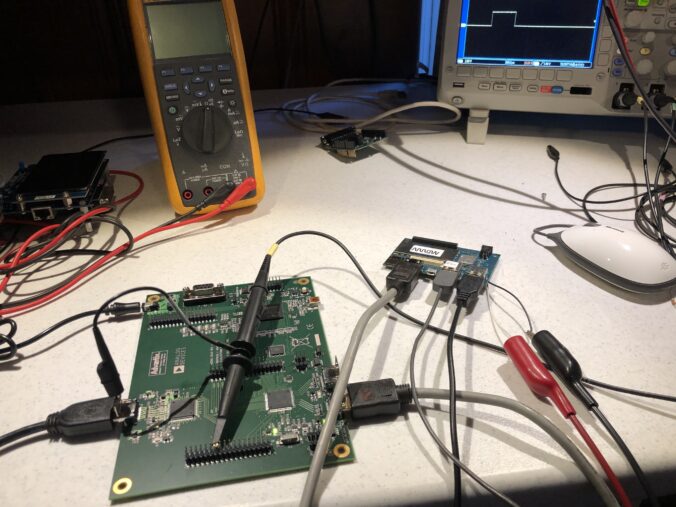
We could just open a monitor and tap into the vertical sync line from whatever decoder it is using. That’s not a bad way to go, but I wanted to study HDMI more closely and have more options for control, so I picked up this eval board, though not from Digikey. At that price I might have just sacrificed a monitor. Still, it’s a pretty neat little setup:
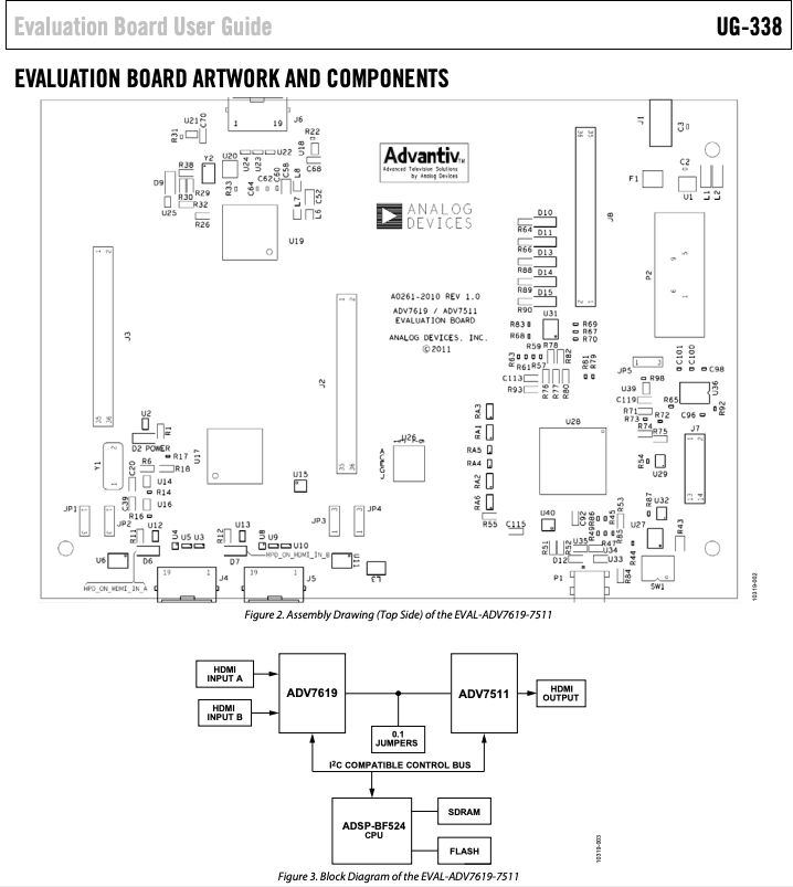
An ADV7619 decodes the HDMI into sync, clock, and pixel lines. An ADV7511 re-encodes those lines to HDMI. And an onboard MCU manages both, letting you peek at and change all the registers. All the lines are also brought out to handy headers for easy monitoring and experimentation.
Be forewarned, the documentation and support are utter crap. This has increasingly become the norm in electronics as the industry consolidates. Even lines with good support tend to become crappy once someone else acquires them and integrates everything into their existing support system. The “synergistic paradigm of shit”, I like to call it, but I digress.
The board comes with a card that lists the wrong part number and a dead URL link:
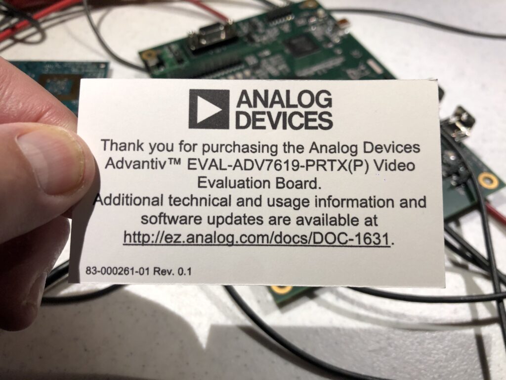
If you follow in my footsteps, you can save some time and find the supposedly current list of docs and tools here. Further, if you are running Windows 10, don’t bother with the official installer. The only version of the GUI software that can find a serial port and communicate on Windows 10 is “AVESBlue”, which is a separate installer.
Once you get AVESBlue running you will see that it doesn’t seem to parse out some of the most useful messages from the eval board firmware, so you’ll want to scrounge up an old USB->RS-232 cable and just hook up that to the DB-9 on the board.
I’m not sure what to use as a terminal program on Windows any more, they seem to have all gone the way of the dinosaur. But on Mac or Linux, you can still use “screen” as a down and dirty one:
% ls /dev/tty.*
/dev/tty.Bluetooth-Incoming-Port	/dev/tty.usbserial-1420                                     % screen /dev/tty.usbserial-1420 115200
Opens a simple terminal. To exit, enter
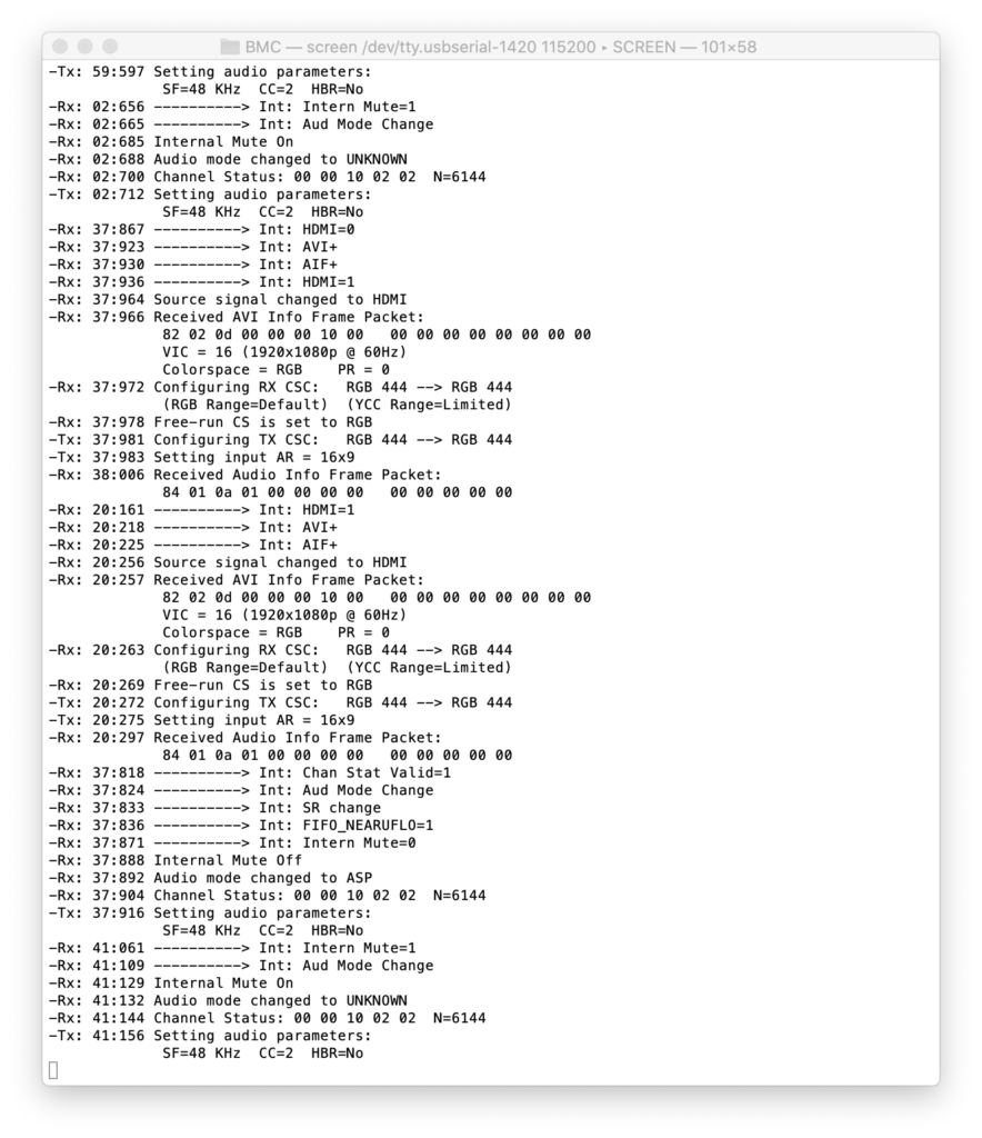
One caveat is HDCP, the copy protection scheme supported by HDMI. The HDMI output on my Macbook uses HDCP. We aren’t a licensed HDMI adopter, so we have no HDCP keys to report from our board. If you use this setup between my Mac and a monitor, the monitor will work for a few seconds, then the system will black out and the HDCP error will be reported to the terminal.
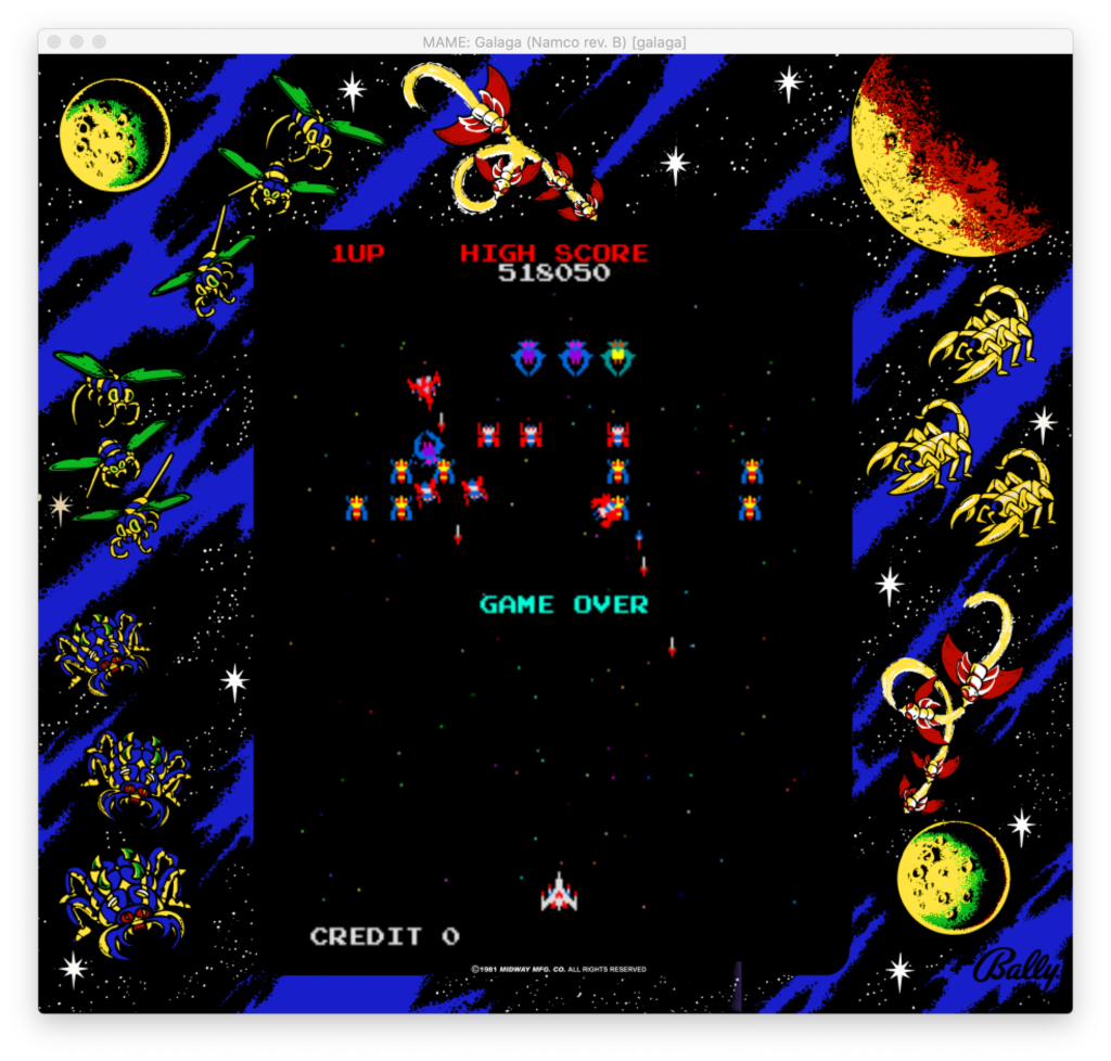
As an initial stand-in, I used a Qualcomm Dragonboard running Linux I had lying around. OK, I usually have it setup to play vintage arcade games and my last game of Galaga before I took it apart for this sucked, but don’t judge me!
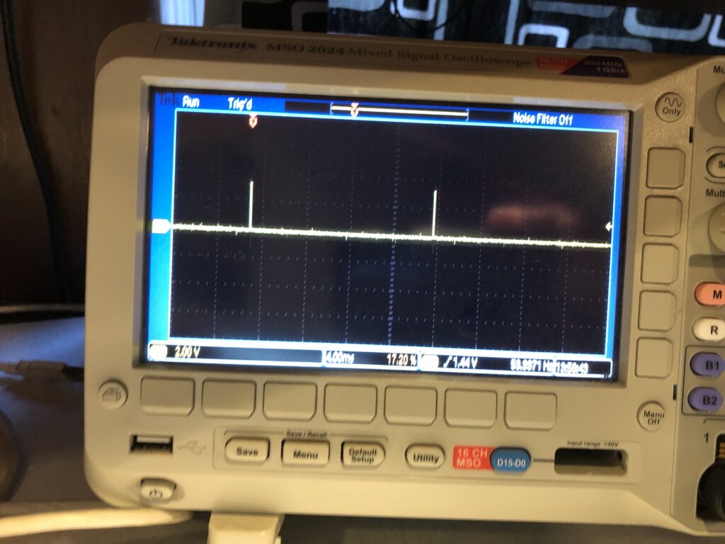
Anyway we get a nice V-Sync signal:
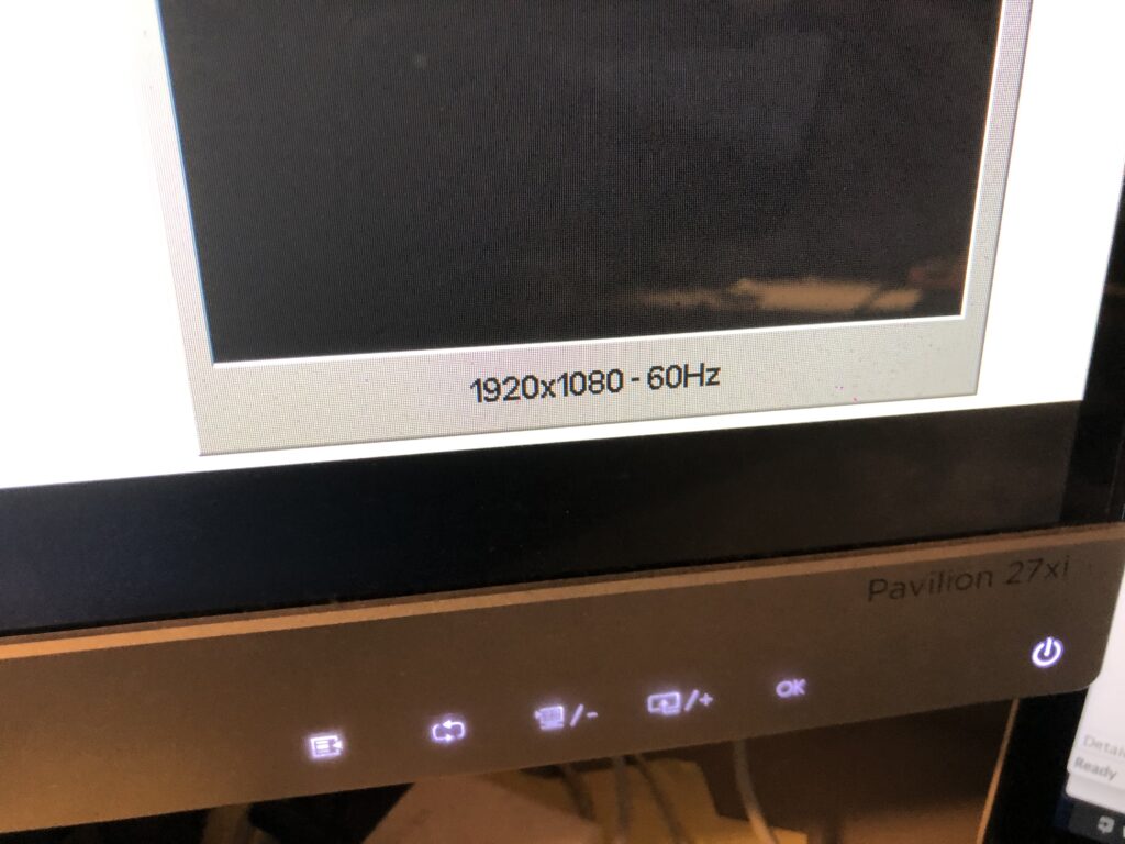
That matches the reported frame rate of the monitor:
And the signal is a nice solid 3.3V, with a reasonable duty cycle:
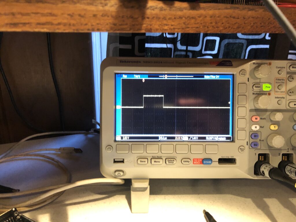
So a short jumper directly to our Sync Input worked fine. It is worth reiterating that there are two assumptions with this scheme:
- The source isn’t HDCP protected
- HDMI decoded VSYNC has a stable, repeatable relationship to the actual camera capture VSYNC
From still another digital imaging project, I have an old Canon EOS M camera (circa 2012), and both those assumptions hold true for it, though my neighbor looked at me like I was insane when I asked them if they had a mini HDMI cable I could borrow.
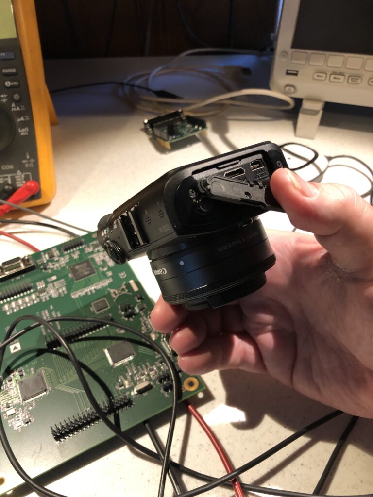
It seems reasonable that both assumptions will hold true for most consumer and semi-pro cameras. High end pro gear isn’t a problem because it generally already outputs the sync information we want.
With external sync available you would think we are in the home stretch, but there is a somewhat unexpected content creation mini-crisis we need to address first.
Leave a Reply