What can I say, waking up new hardware is always fun, particularly when it goes smoothly. I wasn’t quite sure if I really wanted to go with the Arduino ‘stackable shield’ connectors or not, so I had the CM (contract manufacturer) leave those and the DB-25 connector off the cards they assembled for me.
I started to panic slightly putting in the stackable Arduino style connectors. The hole size everyone seems to use is a bit snug. The connector doesn’t just drop in, you have to press and wiggle a little. The idea is to hold the pins well aligned for the board below and the board on top, but I made a note to increase the hole size slightly when I reorder boards.
First, the tolerance is a bit tight for an outside CM to easily assemble. Second, the little bastard drew blood. When one of the connectors did finally slide into its spot, I jabbed my finger.
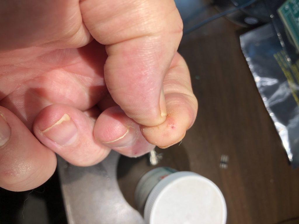
Give me a boo-boo and vengeance will be mine!
Anyway, once the connectors were installed I next hooked 5V directly to the board and checked the onboard +/-9V supply, both with a meter and the scope. When those looked good I went ahead and installed the board on our ARM board.
You might recall from our schematic that the DAC channels are used a little differently than with the TI DAC eval board we first tested on. So I changed the code in scan.c to match, and checked the DB-25 output with the scope.
With X, Y, R, G, and B all working, I next initialized and tested the shutter and blanking lines with the scope. Again, no problem. Same with the 3 spare color channels. Eager to see things go, I finally plugged in the ILDA projector:
I’d been just using the red channel for most my testing and had forgotten how bright this projector is in white (it overwhelms my cell phone camera) and, damn, my lab chair is squeaky, but it is always gratifying when everything works as expected first time.
With the core functions out of the way, I next checked out the new features. Although they aren’t nearly complete, I created placeholder modules for both Sync and DMX to test those parts of the hardware.
For sync, I just hooked OUT to IN with a jumper:
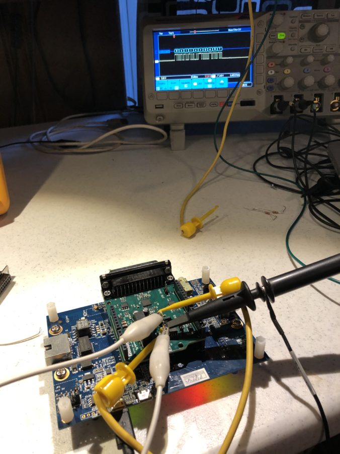
Then I toggled the OUT line in the firmware and reported what I read on the IN line using the debug trace function. DMX wakeup was similar, but it is a differential pair so I used two jumpers, as you can see at the picture at the top of this post.
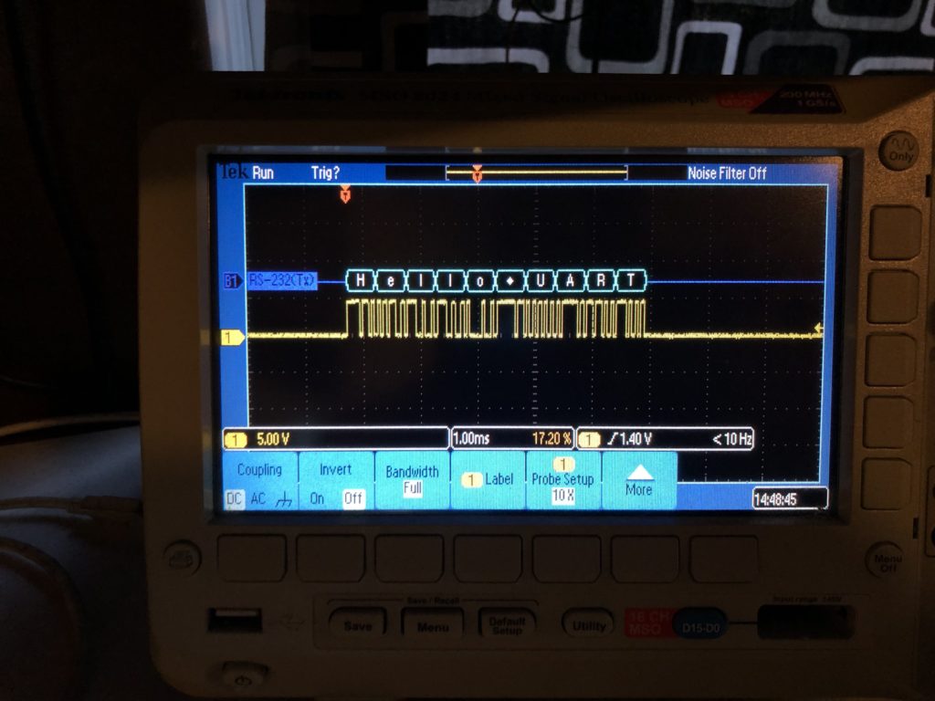
I’ll just say it. The ST HAL Library UART library code is utter crap. We’ll have to write something from scratch when we do DMX for real, but the ST code is good enough to test the DMX hardware functionality. I setup a FreeRTOS timer to send a test message via DMX once a second, then setup a break point to see that the message received matched what I sent at DMX’s 250kbit baud rate:
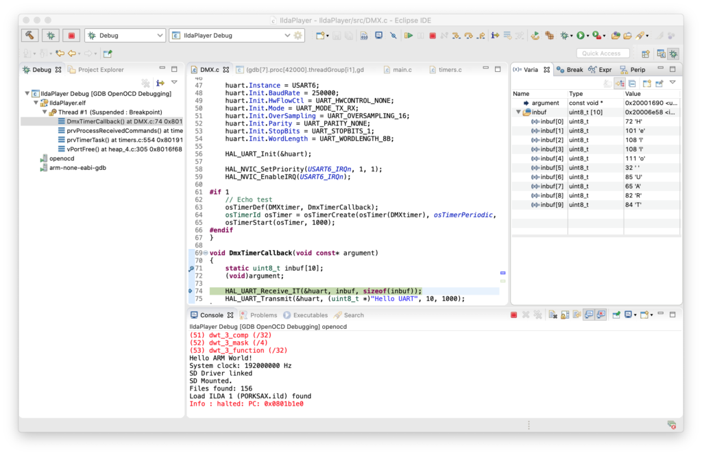
My oscilloscope has a nice RS-232/485 decoder, so I also used that to make sure both sides of the differential pair code be decoded at the expected baud rate and polarity, but I had to switch to a different baud rate than DMX standard. The scope doesn’t support 250kbit, so I just switched the firmware to the closest value the scope has for the test:
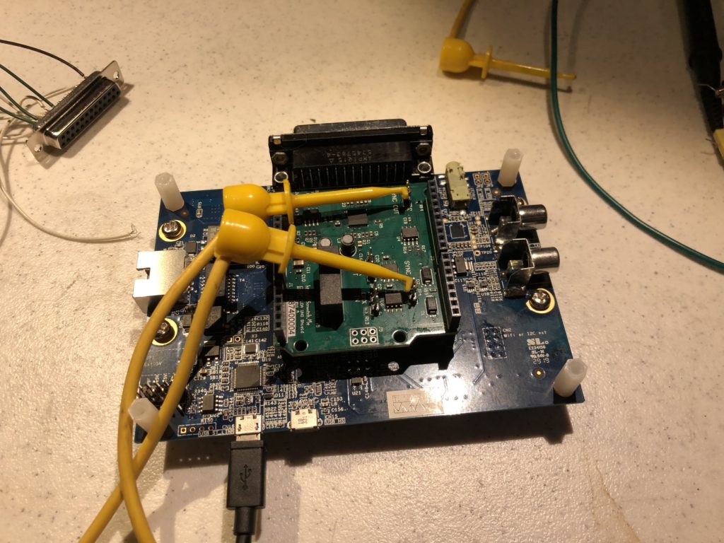
Last, I commented out the Sync and DMX test functions and pushed everything to the repo. I still need to pick up some longer standoffs from McMaster Carr so the assembly sits on legs, not our card:
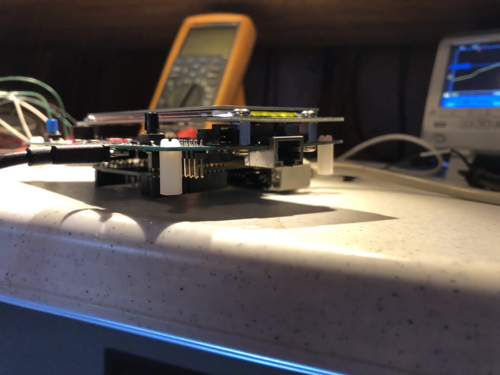
And, at some point, I’ll want to get locking hardware for the DB-25 connector. But now that we have a solid controller module it is time to head to YLS Entertainment and take a first stab at the synced video effect!
Leave a Reply