In our last session we got the display up and running. I got a chunk of time both Sunday and Monday night to add a bit more.
First, I did a little house cleaning. I found that I was fixing quite a few bugs in the “HAL” peripheral drivers from ST.com, so I checked and found that the Eclipse templates we used to frame in the project are a little out of date. ST has a version from February 2020 you can download as part of the STM32F7 Cube MCU Package here. The release notes list some of the bugs I already fixed, so updated the files in our project and tweaked the API calls we are using that have changed.
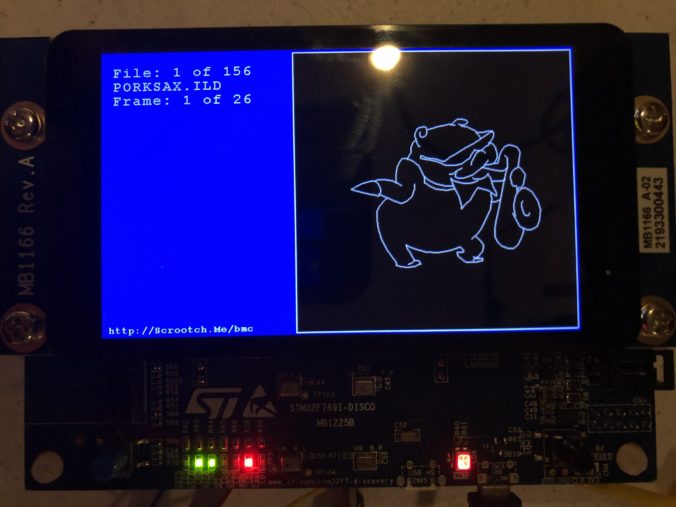
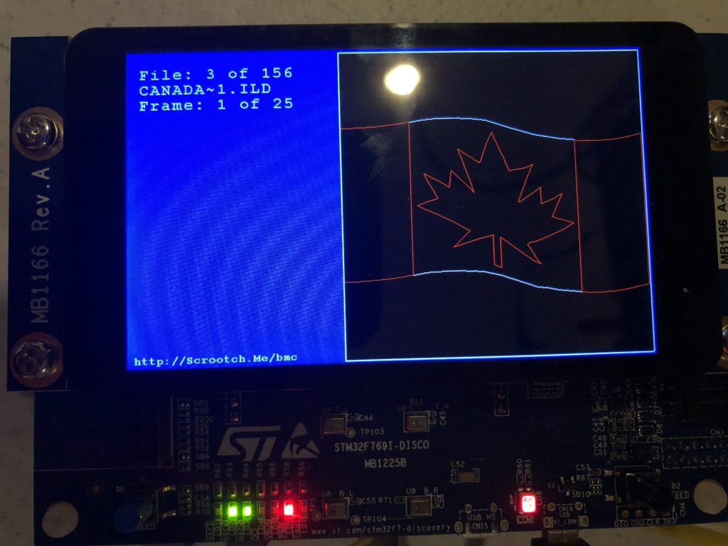
With that out of the way I brought up a the MicroSD card slot and a FAT file system. I actually wrote a nice file system for another project, but I’d have to check with the copyright holder to use it here, so I stuck with the one ST uses in their samples, FatFs, which is from here. None of the ST examples I could find used long file names, and there were some compilation and driver problems when I first set that option in the fs_conf.h, but nothing too hairy. I threw 150 or so ILDA files on a MicroSD card and, as you can see, filenames longer than the old DOS 8.3 (ex. CanadaFlag.ild) work fine:
Next I brought up the capacitive touch display, which relies on a FT6x06 chip from Focal Tech. The datasheet is here. It’s cooler than I expected, and two contact detection works well, so we’ll try to do some gestures for control soon. But for now I just have a cursor you can drag around the screen.
With a display, data storage, and touch input working, I started to frame in a better sample in earnest. I put together an ILDA file loader that normalizes all files into the “ILDA Format 4” (3D, true color) and caches them into SDRAM for scanning.
I then updated the simple scan code I used for testing the DAC so that it is using the cached data and ILDA_FORMAT_4 structure and can be pointed to different frames. Last, but not least, I added a simple frame renderer for the LCD so we can see what is going on.
The function supposedly handles color, though I have very very colorized ILDA files to test:
And those are all crap. When we get around to an editing tool we should colorize all these old graphics from LaserMedia’s early 1980’s Devil Went Down to Georgia module we did for a laser/fireworks show at the racist mother ship, Stone Mountain. Troubled context not withstanding, it remains one of the best laser graphics presentations I have ever seen, in no small part because Disney was laying off animators at the time:
Enough nostalgia. At this point, we have a card that:
- Shows a splash screen
- Scans the installed SD Card for all available ILDA files in a folder named “Graphics”
- Loads all the frames from the first one into SDRAM
- Starts scanning the first frame
To show that touch input is working, you can also touch the screen and drag around a little cursor square:
Yes, it would be nice if I’d wired touch up to select files and frames. And yes, after having gone to the trouble of supporting long file names I still put up DOS 8.3 names on the display because I haven’t written a decent font manager yet. But my day job has been a bit busy lately (sneaking this post in during a lunch break). Still, we have quite a bit working. As always, you can pull the code directly from the git repo, but it is worth covering the scan code just a bit.
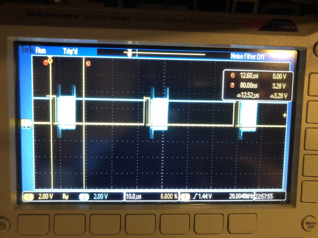
The first thing worth noting is how /CS, or “chip select” is handled for our DAC. You can see it in this scope trace. Yellow is chip select, blue is SPI clock:
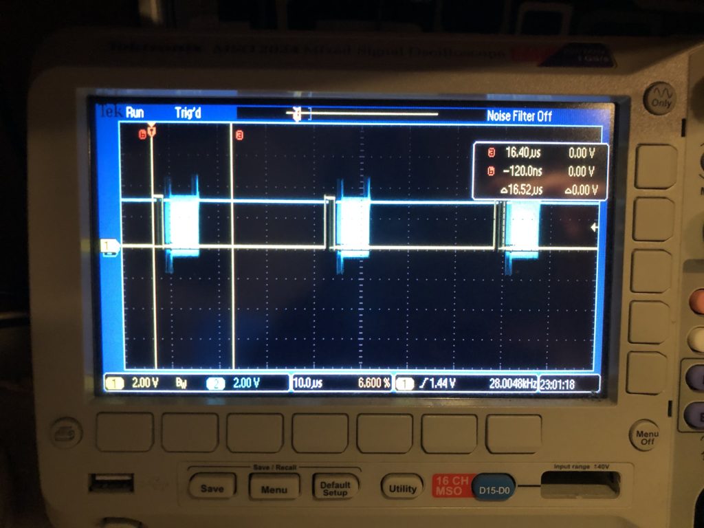
The /CS line only turns off for short intervals that match our scan rate. This is intentional. We are writing all 8 DACs every time. The outputs take effect when the /CS line goes high, so that is the first thing we do each time interrupt. This synchronizes our DAC value changes very tightly to a very stable clock – something we will want for our intended video effect.
The interrupt handler next calculates all the new DAC values, asserts /CS, and starts transmitting over SPI. That is a DMA driven transfer, so the interrupt handler returns before the SPI clocking even starts, freezing up the processor to do other stuff, like ethernet, USB, DMX, etc. As it is, we are fitting very comfortably in the 28 kHz scan rate time windows. The vertical cursors show what a 60 kHz window (the fastest scanners I could find) would be and, again, this should be no problem, particularly since we are running a lot of inefficient HAL code in the handler. With that in mind, even 80 kHz looks pretty obtainable:
But if we want to scan any faster, say 100 kHz, we’ll need to mod the base card so we can do SPI with an onboard controller on the STM32F769’s other, faster, peripheral bus. As we discussed when we sketched the card out, the lines on the Arduino expansion connector can only go 25 MHz, half the speed that the DAC can accept data.
Another odd thing you might see in the code is this, in the interrupt handler:
		int32_t val;
		val = pntData[curPoint].x.w;
		val += 32768;
		DacOut[1] = val >> 8;
		DacOut[2] = val & 0xFF;

		val = pntData[curPoint].y.w;
		val += 32768;
		DacOut[5] = val >> 8;
		DacOut[6] = val & 0xFF;

		int16_t idx;
		if (CurrentFrame->numPoints > 4)
		{
			idx = curPoint - 4;
			if (idx < 0)
				idx += CurrentFrame->numPoints;
		}
		else
			idx = curPoint;

		if (pntData[idx].status & 0x40)
			DacOut[9] = DacOut[10] = 0;
		else
			DacOut[9] = DacOut[10] = 0xFF;
X and Y handling isn’t optimized (we’ll get to it!) but pretty clear. The data is fetched, shifted for a unipolar DAC, then put in the message in “big endian” order. But blanking information is then shifted to come from 4 points earlier in the scan. This is because most these graphics are old. They come from a time when blanking (laser invisible) was done with a 3rd scanner, or galvanometer. The diode lasers in the projector I am using are faster.
When we scan these images at 14 kHz (what they were originally created at), we need to shift about 2 scan intervals later to get the intended blanking effect. Up at 28 kHz, it becomes 4 scan intervals (what the code is doing above).
From what I can tell, there are really three generations of laser graphics content floating around. Old content like this, created for mechanical blanking and color. Brand new content, created for diode laser blanking and color control, which is faster, and a generation in between, that used acousto optical defection, or modulation. This technology appears to have largely disappeared because the diode technology is cheaper and has less energy loss, but it was faster. So graphics created for it would generally need blanking and color changes shifted in the opposite direction from what we are doing here.
The moral of all this is we are going to want to generalize this mechanism and expose control of it so that people can easily utilize older graphics.
Lunch break is over, but I’m hoping to see our PCBs from FedEx today and get them sent to the contract manufacturer tomorrow. I should be able to get another chunk of time to move the system forward again soon.
Leave a Reply