For anyone bothering to read this drivel, we knew after this test that we could freeze the rolling shutter effect as Marty Canavan from YLS Entertainment requested.
But Marty doesn’t want to use the effect for a single video shot, where everything can be dialed in manually just prior to each video take. He wants the ability to use the effect multiple ways in one continuous video take. Effectively a live performance. So we need a way to sync our system to the video.
Conceptually this is pretty simple, we want to set everything up, then gate our scan timer off of the camera’s vertical sync (when the camera is about to scan the next frame). We don’t need to do this continuously, just once to kick off each effect.
Vertical sync is a concept that dates back to the earliest forms of television:
The picture lines were scanned one at a time, top to bottom, and ‘vertical sync’ is the time interval when the scan has to be deflected back from bottom right to top left. The technology has changed dramatically, but the basic need, synchronize with the start of the next frame, has never gone away although gamers tend to think of it as the choice between frame rate and tears in the photorealistic urinals in their game:
Back in the dark ages I worked on first generation video conferencing equipment and early consumer digital cameras as part of Canon’s Advanced Digital Imaging group, so these concepts aren’t new to me. But I haven’t really paid close attention to the technology since, so my first step in this process was to look at the side of the camera, read “HDMI out”, and then Google the pinout:
Superficially, the scheme seems pretty clear. Red, green, and blue color information is clocked down three “TMDS channels”. DDC, or “display data channel” is just an I^2C interface so the HDMI source can read brand and capabilities info from the display (or “HDMI sink”). The CEC line is a single wire communication line for sharing remote control type operations. But there are no obvious “sync” lines in the physical interface.
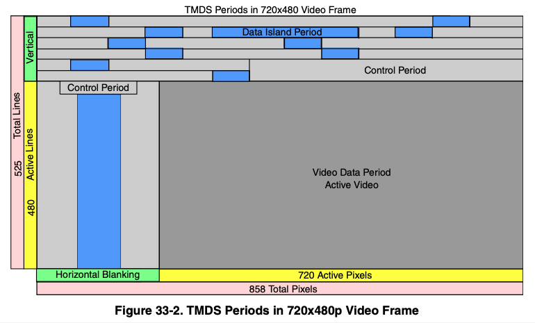
After a little specification reading two things seemed clear:
TMDS, or “transition minimized digital signaling”, is very clever
The digital stream has to be decoded to recover horizontal and vertical sync
I’ll spare you a huge dose of ‘a lot of people don’t know’ lecturing for a subject I, myself, am about one wikipedia article ahead in, but the basic scheme is as follows: 8 bit video information being clocked serially is very noisy because all the 1-0-1 transitions are high frequency square waves. TMDS stretches 8 bits to 10 bits using an algorithm that minimizes high frequency noise generated (“transition minimized”).
A 10 bit word has 1024 possible bit combinations. TMDS reserves or forbids 558 of those combinations (too noisy, or they make it hard to find framing). 2 of the possible combinations are used for data framing. 4 of the combinations are reserved to toggle 2 control bits. The remaining 460 combinations are used to encode 8 bit data in more noise friendly ways.
The two control bits, C0 and C1, are of the most interest to us. On DVI and HDMI, they carry H-Sync and V-Sync on TMDS channel 0. The control bits on the other channels are designated CTL0-3 and, on HDMI, indicate what kind of data (video, audio, or aux) is currently being transmitted.
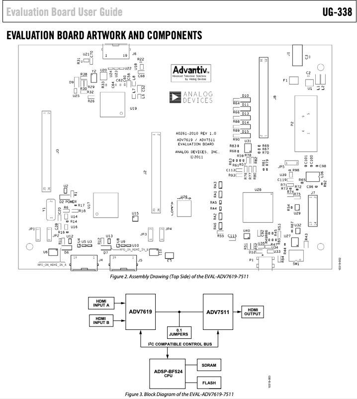
Again, pretty clever, and I’m glad I read the specs. If you don’t have a way to access the “HDMI Adopter Extranet” (I do work with some current licensees), the NXP docs for their HDMI peripherals look like a pretty good surrogate. In fact, quite a few of the illustrations look identical:
Sorry NXP, but I figured if I threw you under the bus, HDMI.org would leave me alone for anything I put in this post. Anyway…
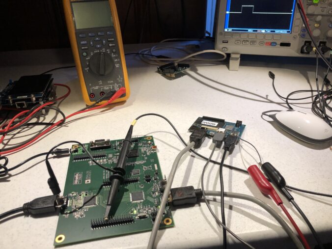
We could just open a monitor and tap into the vertical sync line from whatever decoder it is using. That’s not a bad way to go, but I wanted to study HDMI more closely and have more options for control, so I picked up this eval board, though not from Digikey. At that price I might have just sacrificed a monitor. Still, it’s a pretty neat little setup:
An ADV7619 decodes the HDMI into sync, clock, and pixel lines. An ADV7511 re-encodes those lines to HDMI. And an onboard MCU manages both, letting you peek at and change all the registers. All the lines are also brought out to handy headers for easy monitoring and experimentation.
Be forewarned, the documentation and support are utter crap. This has increasingly become the norm in electronics as the industry consolidates. Even lines with good support tend to become crappy once someone else acquires them and integrates everything into their existing support system. The “synergistic paradigm of shit”, I like to call it, but I digress.
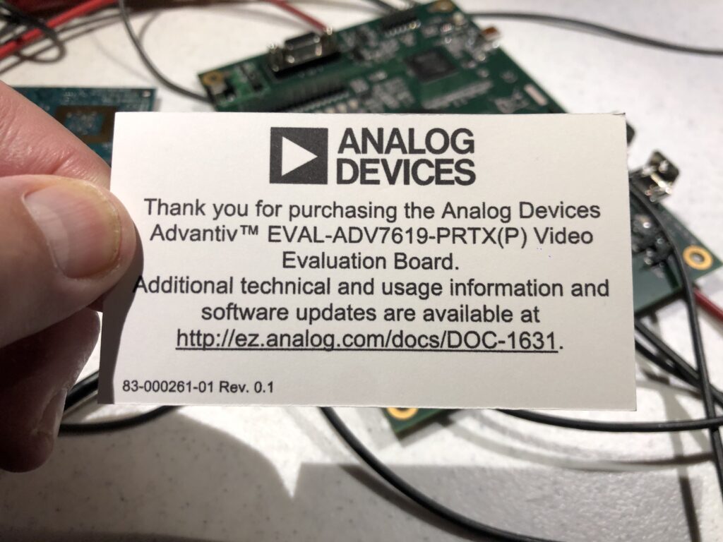
The board comes with a card that lists the wrong part number and a dead URL link:
If you follow in my footsteps, you can save some time and find the supposedly current list of docs and tools here. Further, if you are running Windows 10, don’t bother with the official installer. The only version of the GUI software that can find a serial port and communicate on Windows 10 is “AVESBlue”, which is a separate installer.
Once you get AVESBlue running you will see that it doesn’t seem to parse out some of the most useful messages from the eval board firmware, so you’ll want to scrounge up an old USB->RS-232 cable and just hook up that to the DB-9 on the board.
I’m not sure what to use as a terminal program on Windows any more, they seem to have all gone the way of the dinosaur. But on Mac or Linux, you can still use “screen” as a down and dirty one:
% ls /dev/tty.*
/dev/tty.Bluetooth-Incoming-Port	/dev/tty.usbserial-1420                                     % screen /dev/tty.usbserial-1420 115200
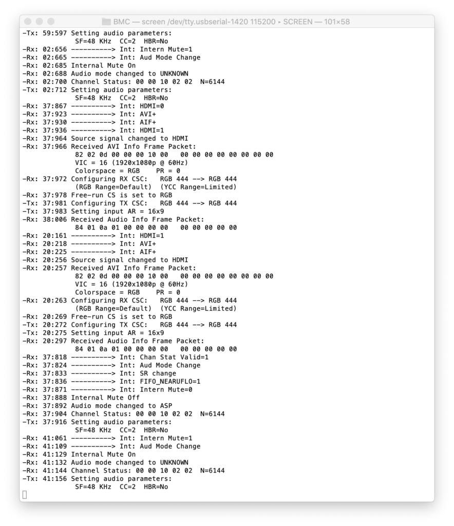
Opens a simple terminal. To exit, enter a followed by d. Over RS-232 the board gives status messages and offers commands to control the pass-thru application and directly manipulate chip registers:
One caveat is HDCP, the copy protection scheme supported by HDMI. The HDMI output on my Macbook uses HDCP. We aren’t a licensed HDMI adopter, so we have no HDCP keys to report from our board. If you use this setup between my Mac and a monitor, the monitor will work for a few seconds, then the system will black out and the HDCP error will be reported to the terminal.
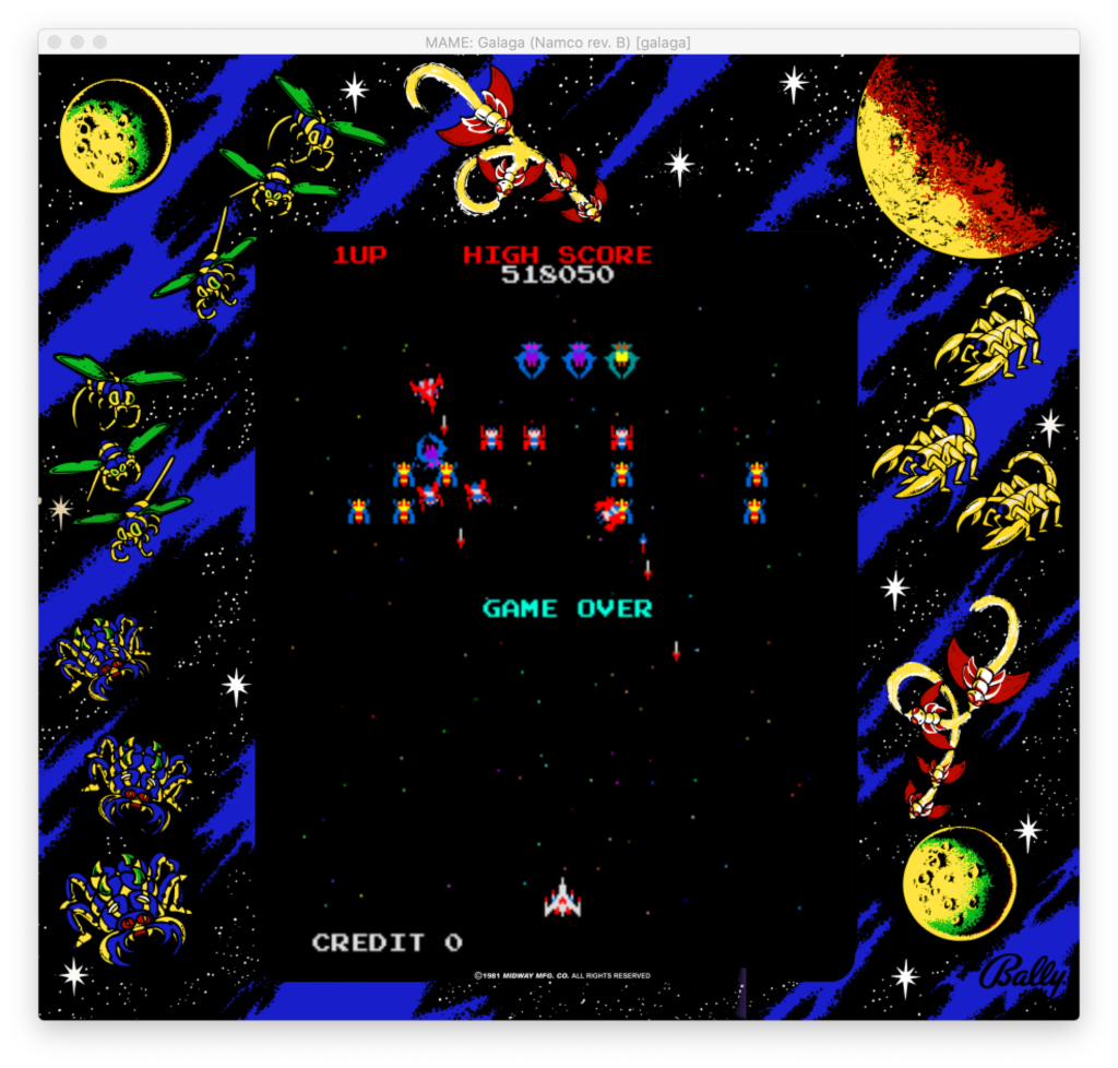
As an initial stand-in, I used a Qualcomm Dragonboard running Linux I had lying around. OK, I usually have it setup to play vintage arcade games and my last game of Galaga before I took it apart for this sucked, but don’t judge me!
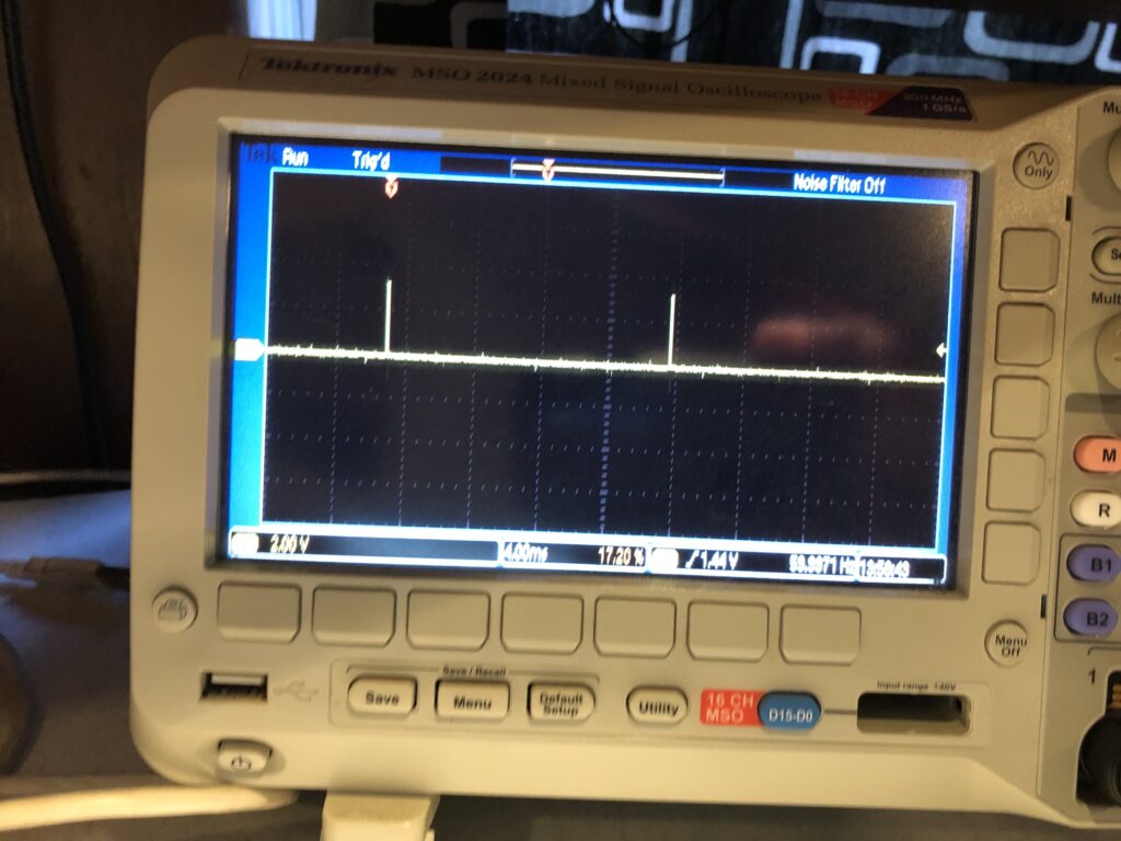
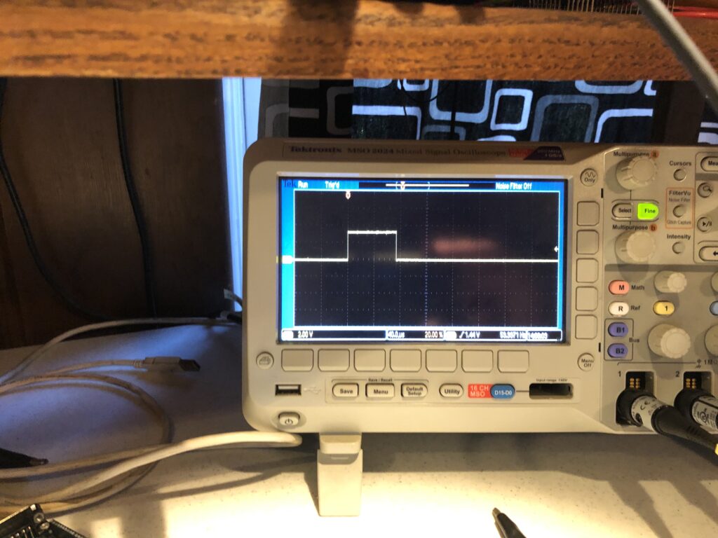
Anyway we get a nice V-Sync signal:
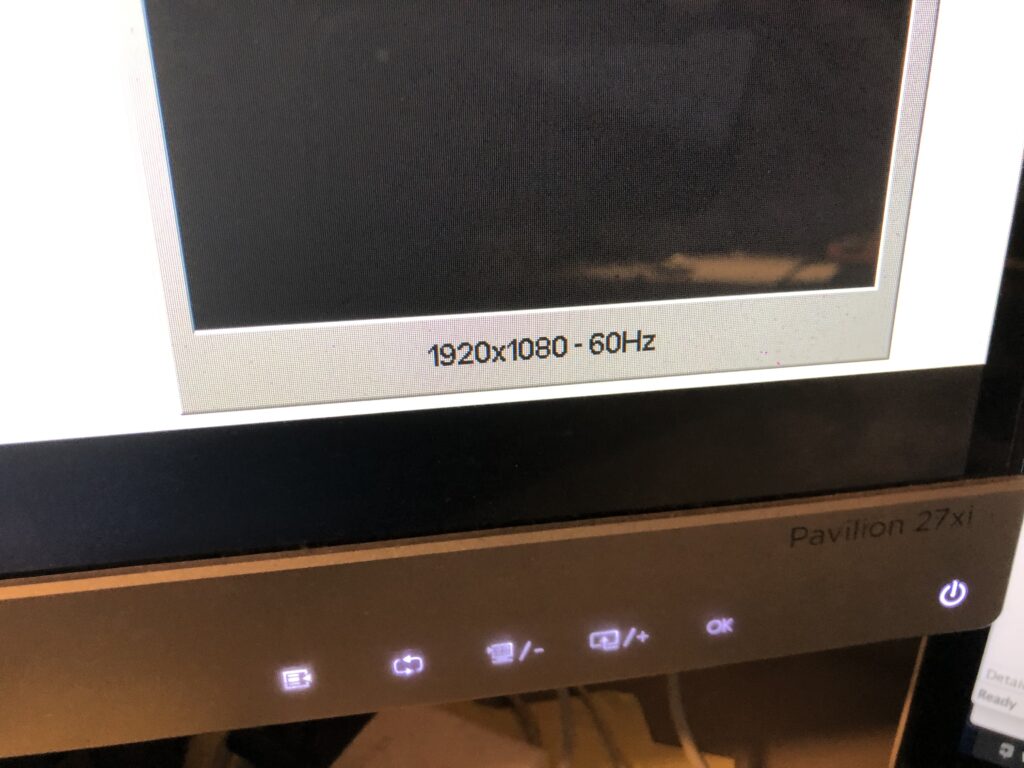
That matches the reported frame rate of the monitor:
And the signal is a nice solid 3.3V, with a reasonable duty cycle:
So a short jumper directly to our Sync Input worked fine. It is worth reiterating that there are two assumptions with this scheme:
The source isn’t HDCP protected
HDMI decoded VSYNC has a stable, repeatable relationship to the actual camera capture VSYNC
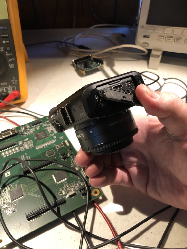
From still another digital imaging project, I have an old Canon EOS M camera (circa 2012), and both those assumptions hold true for it, though my neighbor looked at me like I was insane when I asked them if they had a mini HDMI cable I could borrow.
It seems reasonable that both assumptions will hold true for most consumer and semi-pro cameras. High end pro gear isn’t a problem because it generally already outputs the sync information we want.
In the last post I mentioned a need to add video sync to really hit our rolling shutter effect out of the park. I have an eval board coming for an HDMI decoder/encoder pair, but had a little time on Monday so I went ahead and fleshed what is sometimes called a “transform”, the ability to position, scale, and rotate an image we are projecting.
Compared to a modern first person shooter game…
What we are going to do is pretty simple. Still, the first time I was shown a linear algebra rotation matrix in the early 80s I thought it was magic, and the feeling has never completely gone away.
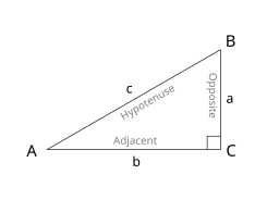
There are a fair number of textbooks and tutorials floating around, but for our purposes it starts with trigonometry, the wonderful world of right triangles. Although it is undoubtedly not PC, I still remember the trig relationships with “I can measure the circumference of the earth with this stick, a tape measure, and my good buddy SOH CAH TOA!” It turns out you can’t, at least not super accurately, because the earth is not really a sphere, but in the world of vector laser graphics, SOH CAH TOA is, indeed, our good friend!
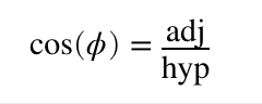
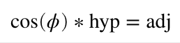
In the mnemonic, S, C, and T stand for sine, cosine, and tangent. O, H, and A stand for opposite, adjacent, and hypotenuse. The basic idea is that if you divide the lengths of two of the triangle’s three sides, you will get a specific ratio, and that ratio always represents the same angle. For example, the cosine of angle A above is the length of the adjacent (b) divided by the length of the hypotenuse (c). Or, CAH for short:
This is also our first laser rotation.
The cosine for zero degrees is one. This is pretty easy to visualize with our triangle above. If b/c = 1, then b and c are the same length, making angle A = 0 degrees.
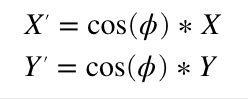
Now that you have a flat triangle in your mind, pretend it is our laser projection viewed from above. The hypotenuse is a line in our graphic ending at coordinate {c, 0} (where the hypotenuse meets B). We want to rotate it around our Y axis (at connection A). We know the length of our hypotenuse (c) because we have an X coordinate, and we know the angle we want for rotation. Since we have two parts of CAH, we can rearrange the formula above and solve for the part we don’t have:
If we want to rotate 45 degrees, cosine is approximately 0.707, so our new coordinate is {0.707*c, 0}
Rotating around the X axis is very similar. We just use the cosine of the desired angle to scale our Y coordinate instead of X. This means that if we only wanted to rotate around the X and Y axes, we’d only need two multiplies and our formula would look like this:
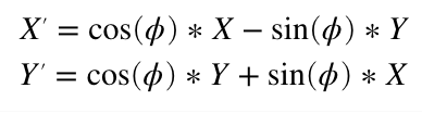
Rotating around the Z axis, the line coming towards us, is a bit more complicated. I’m not going to duplicate one of the many tutorials online, but you can work it out very much like above (hint, thinking about two triangles always helps me) and you should end up with a Z rotation formula something like this:
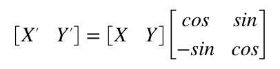
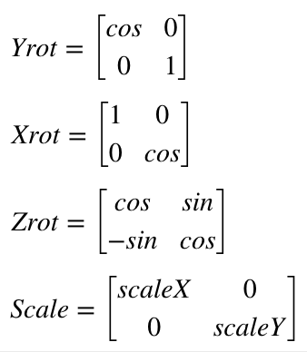
Instead of a formula, we can express this as a linear algebra matrix. Z rotation is:
When you multiple two matrixes together you “multiply and accumulate”. Basically multiplying and adding horizontal rows from the left operand with vertical columns from the right operand.
So the matrix above is the same basic steps as the four multiplies and two adds (we use a negative value to get a subtract) from the Z rotate formula we derived earlier. What makes the matrix magic is two things. First, most the operations we are interested in can be expressed by one. For example:
Second, you can combine them. Matrix multiplication is not commutative. That is, A*B will generally not give the same answer as B*A, but you can typically combine rotation and transform matrixes, provided you multiply things in the right order. So we could multiply the operation matrixes by each other and derive a single matrix. Then do all those operations on each point in our image with the same four multiplies and two additions as our Z rotation above. Like I said, magic!
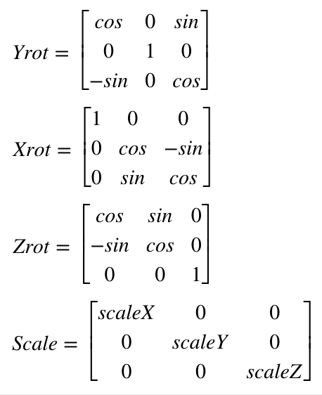
If you read a tutorial on this subject they will not normally use a 2×2 matrix, but something called homogenous coordinates and a 3×3 matrix for 2D graphics. This lets you do things like position the image as well. But we won’t mess with that until we address things like perspective later. For now we will just stick with a simple rotational matrix. However, we will expand to 3×3 to accommodate 3D graphics, since ILDA images can contain a Z position for each coordinate as well. If you worked out 2D Z rotation for yourself above, you won’t be surprised to see that our matrixes for 3D look like this:
Now that we have an idea what we want to do, we have to pick a way to code it. As it happens, we have two really good possibilities with our STM32F769 MCU. The ARM core has something called the DSP instructions and this chip has a double precision floating point unit (FPU). There are pros and cons to both approaches.
The DSP instructions are very fast (multiply and accumulate in a single instruction that executes in a single clock cycle), but it is integer math (whole numbers only). So you usually have to scale operators up and down and give some thought to your target ranges. Math library support for the DSP instructions is also a bit sketchy, at least on the free tools we are using. We might still end up back here, but to get things going I went with the double precision FPU to start.
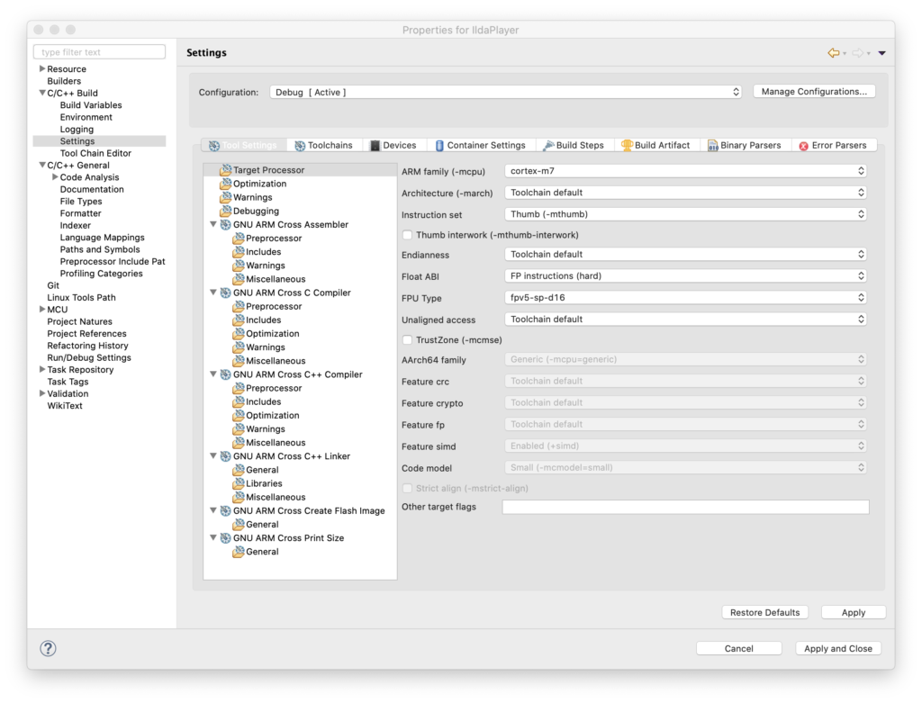
To use the FPU, the first thing we have to do is tell the compiler we want to. Those options are stashed away in Project Settings / C/C++ Build / Settings / Target Processor:
“Float ABI” has to be set to use FP instructions (Hardware) and the FPU type has to be set to the one on our MCU (harder to lookup than you might think). In addition to telling the compiler to use it, like many peripherals on our MCU, the FPU also has to be enabled. This already conditionally happens in an existing function called SystemInit():
  /* FPU settings ------------------------------------------------------------*/
  #if (__FPU_PRESENT == 1) && (__FPU_USED == 1)
    SCB->CPACR |= ((3UL << 10*2)|(3UL << 11*2));  /* set CP10 and CP11 Full Access */
  #endif
With hardware floating support on, the next thing to do is to take a stab at our first implementation of a transform as a structure we can apply as we scan:
Again, this is really just a placeholder. We will probably make a matrix type at some point, and we’ll eventually want to transform color as well, etc. But this is good enough for a test.
We can position, rotate, scale, control intensity, and add a rotation offset, which I’ll explain shortly. We can also adjust the blanking/color offset. You may recall that I mentioned that graphics from different eras were created with different assumptions about the speed of the blanking and coloring mechanisms. Up to now we’ve been hardcoding a shift for very old graphics played faster than they were originally intended. Now we can change that on a frame by frame basis.
Using all these settings our scan interrupt handler has gotten a bit longer, but is still pretty clear. It still isn’t optimized. But at this point that actually helps:
void TIM2_IRQHandler()
{
if (TIM2->SR & TIM_SR_UIF)
{
TIM2->SR &= ~TIM_SR_UIF;
// Latch the previous values
HAL_GPIO_WritePin(GPIOA, GPIO_PIN_11, GPIO_PIN_SET);
ILDA_FORMAT_4 *pntData;
pntData = &(CurrentFrame->points);
int32_t val;
double d;
double dx, dy, dz;
uint8_t clip = 0;
dx = pntData[curPoint].x.w;
dx *= currentTransform.scaleX;
dx += currentTransform.roX;
dy = pntData[curPoint].y.w;
dy *= currentTransform.scaleY;
dy += currentTransform.roY;
dz = pntData[curPoint].z.w;
dz *= currentTransform.scaleZ;
dz += currentTransform.roZ;
d = dx * currentTransform.matrix11 + dy * currentTransform.matrix12 + dz * currentTransform.matrix13;
val = (int32_t)d;
val += currentTransform.posX;
if (val < -32768)
{
val = -32768;
clip = 1;
}
if (val > 32767)
{
val = 32767;
clip = 1;
}
val += 32768;
DacOut[7] = val >> 8;
DacOut[8] = val & 0xFF;
d = dx * currentTransform.matrix21 + dy * currentTransform.matrix22 + dz * currentTransform.matrix23;
val = (int32_t)d;
val += currentTransform.posY;
if (val < -32768)
{
val = -32768;
clip = 1;
}
if (val > 32767)
{
val = 32767;
clip = 1;
}
val += 32768;
DacOut[5] = val >> 8;
DacOut[6] = val & 0xFF;
int16_t idx;
if (CurrentFrame->numPoints > (uint32_t)abs(currentTransform.blankOffset))
{
idx = curPoint + currentTransform.blankOffset;
if (idx < 0)
idx += CurrentFrame->numPoints;
else if (idx >= (int16_t)CurrentFrame->numPoints)
idx -= CurrentFrame->numPoints;
}
else
idx = curPoint;
if ((pntData[idx].status & 0x40) || clip)
{
DacOut[3] = DacOut[4] = 0;
DacOut[1] = DacOut[2] = 0;
DacOut[15] = DacOut[16] = 0;
}
else
{
double i;
i = pntData[idx].red * currentTransform.intensity;
DacOut[3] = (uint8_t)i;
i = pntData[idx].green * currentTransform.intensity;
DacOut[1] = (uint8_t)i;
i = pntData[idx].blue * currentTransform.intensity;
DacOut[15] = (uint8_t)i;
}
if (pntData[curPoint].status & 0x80)
{
curPoint = 0;
// Is it time for a new frame?
if (NewFrameRequest)
{
CurrentFrame = NewFrame;
NewFrameRequest = 0;
}
// Update transform?
if (UpdateTransform)
{
memcpy (¤tTransform, &pendingTransform, sizeof(TRANSFORM));
UpdateTransform = 0;
}
}
else
++curPoint;
HAL_GPIO_WritePin(GPIOA, GPIO_PIN_11, GPIO_PIN_RESET);
HAL_SPI_Transmit_DMA(&Spi_Handle, (uint8_t*) DacOut, sizeof(DacOut));
}
}
Our processing pipeline is slightly more complicated than the single matrix we described above. It’s broken down into a few steps:
Apply scale to the X, Y, and Z coordinates
Add X, Y, and Z rotational offset
Apply the rotation matrix
Add position
Check for clipping
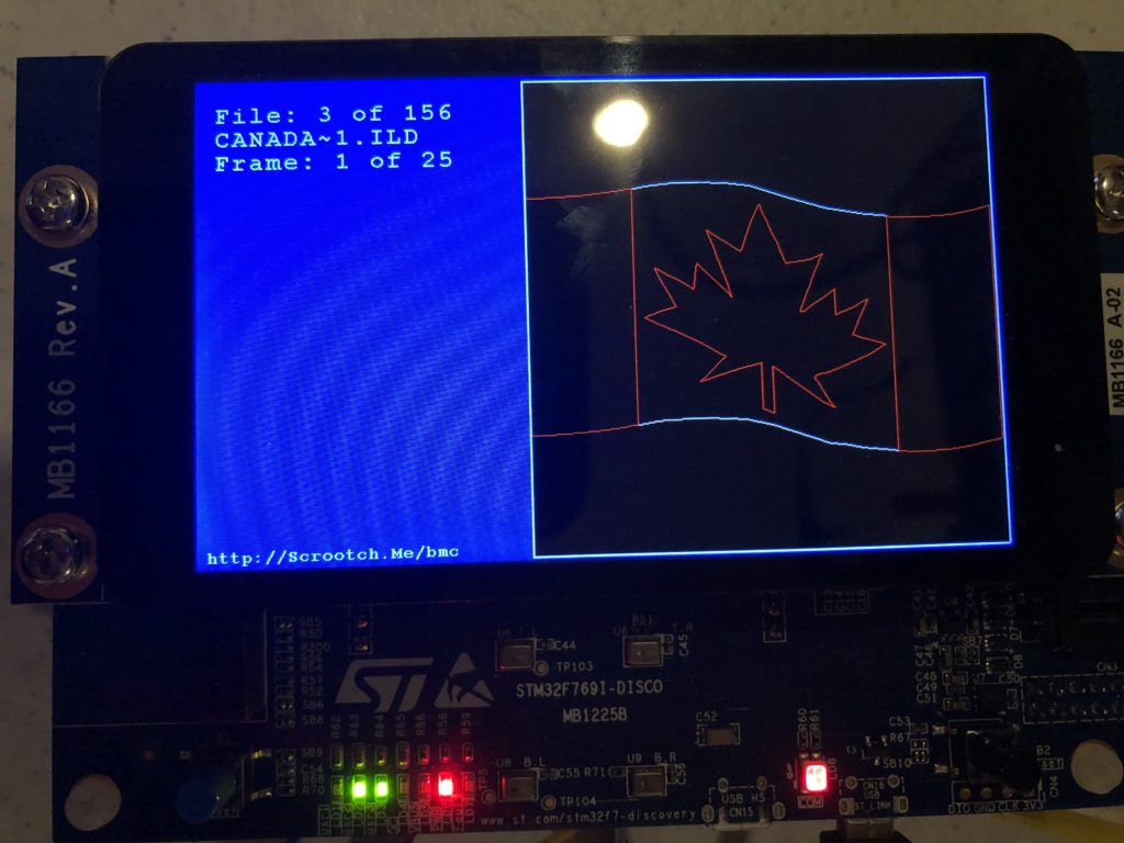
The pros and cons of these decisions are a big subject I don’t really want to go into now. But we will be revisiting this again fairly soon. For now, let’s just call this Laser Bling 101. The first big question is, does it work? Thankfully, the answer is yes:
This flag graphic isn’t great, but it is the only ILDA file with Z values in it I have, and you can see that we are rotating in 3D as we rotate this frame around the X axis. Here is the same 3D image animating and rotating around both the X and Z axes:
The next question is, how is performance? I’d say, not bad at all. Better than I expected without some optimizations, to be honest:
We are using about 16% of the CPU time to scan at 30 kHz, and we still have quite a bit of room for improvement. Now let’s take a quick look at the other parts of the transform.
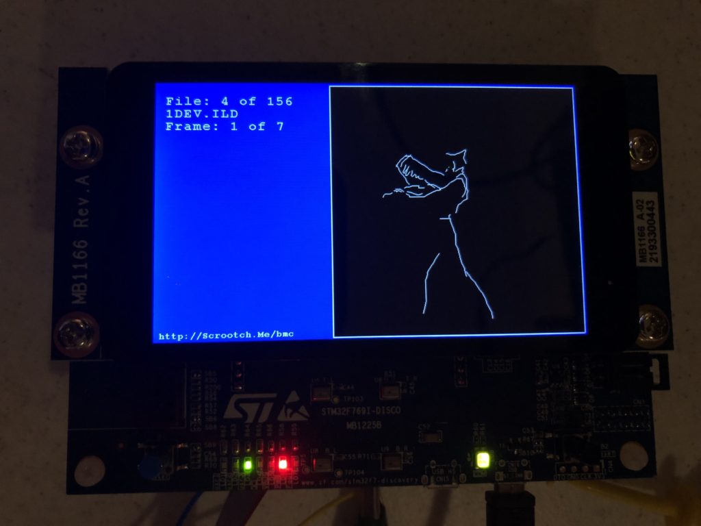
Intensity lets us crank down to 10% so that white images don’t freak out the camera on my phone. We can then scale our favorite sax playing pig down and spin him on the Z axis:
He isn’t quite drawn centered, but is sort of rotating around his center of mass. We could add a little rotational offset to center him up, but let’s add a little bigger positive roY. Now he is rotating around his feet:
If we invert the polarity of the roY, he is rotating around his head:
Positioning lets us shift the whole thing around the available scan angle. If we move too far, the image will clip:
There are a couple schools of thought on how to handle clipping. One is to not scan the clipped points in images. This frees up scan time for other images, making those other images brighter. But we are still going to want to lock to rolling shutters, so we scan the clipped points so there is no time shift, but we blank them out so any squishing or distortion isn’t visible.
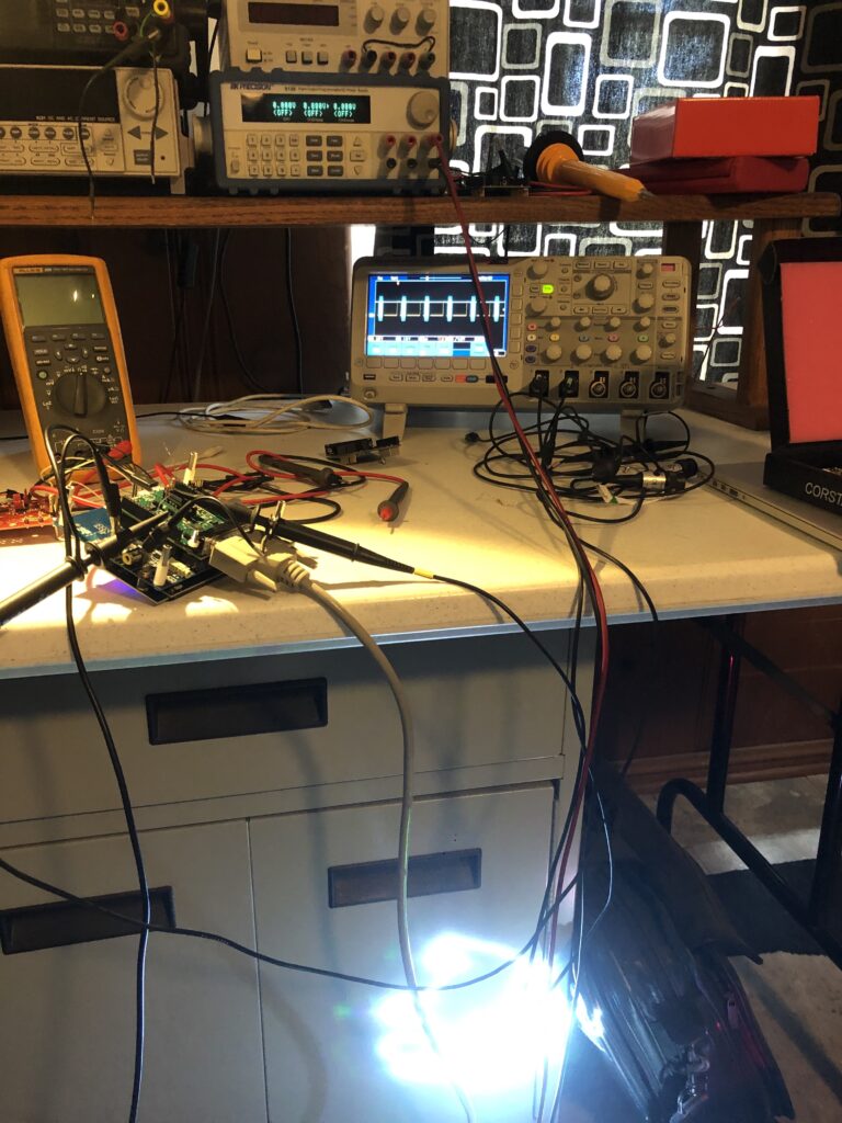
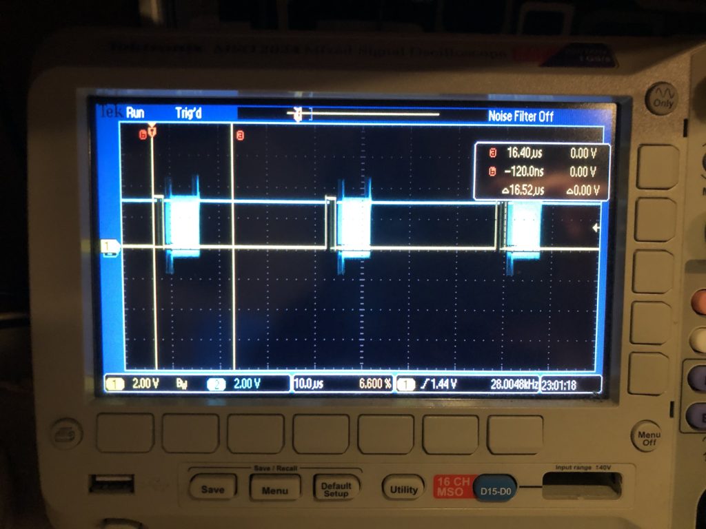
There is a consideration for performance I should touch on. Building our rotation matrix is more intensive than using it. It takes 54 multiplies to combine the X, Y, and Z rotation matrices. That’s not terrible. We typically only need to update the matrix 10 to 30 times per second, not the 30,000 times a second (or more) we use the combined matrix for scanning. But look what happens when I try calling sin() and cos() one time each at the end of each graphic frame:
If we zoom in on the scope we can see that those two calls push our processor utilization to almost 100% for that one scan interval:
If you look at the library source code for, say, sin() you will find it is very complex. It uses one algorithm if you are very close to 0 degrees, basic Taylor series calculations out to a couple of degrees, and then multiple calculations applied to correction tables when the angles get larger.
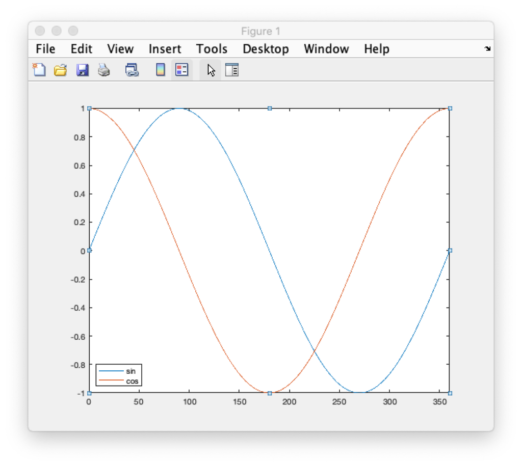
We aren’t going to do that. I pre-calculated a sine table in 0.1 degree steps and stored the results in flash memory as a lookup table. We don’t need a separate table for cosine because we just need to shift 90 degrees in our sine table to get cosine for the same angle:
Going in 0.1 degree steps might seem like overkill, but it gives us more granularity of control in terms of rotation speed and will let us make smoother transitions as we start and stop rotations. If we end up needing even more granularity we have the room for it in flash memory but, for now, rotations are very smooth:
That’s enough for now. Sorry this post was so long. Depending on when the eval card arrives we will either be testing HW sync operations next, or putting together our first host control application.
As I promised in the last post, it was finally time to see where we are on the original problem. On my way home from my day job I stopped off at YLS Entertainment to see how we fair in controlling interaction with the rolling shutter on a good video camera.
Before heading over I did a little prep work. First, I made scan rate real time adjustable and exposed the raw timer reload value on the display and added touch quadrants to control it:
Because we want our scanning to be very low jitter for better rolling shutter synchronization, updating the scan rate well could have been tricky on some MCUs. But the STM32xxx timer peripheral we are using has a really nice feature. You can turn on something they call “preload”, or “register shadowing”. Shadowing is basically a second copy of a timer control register that firmware can read and write, but anything written does not take effect until the next timer update (scan period in our case). This makes smoothly controlling the rate of our scan period timer dynamically very easy.
You can read about shadow registers in the STM32Fxx Timer Cookbook from ST. Another appnote contains a terser version of much of the same info and a few additional tidbits.
In our case the timer initialization code only required one additional line to turn on the ARPE control bit:
        // Timer 2 is our master controller
	TIM2->PSC = 0;
	// Initialize the period to get 28 kHz as frequency from 96MHz
	TIM2->ARR = SCAN_MIN_ARR;
	// Select Clock Division of 1
	TIM2->CR1 &= ~ TIM_CR1_CKD;
	// buffer ARR
	TIM2->CR1 |= TIM_CR1_ARPE;
	// CMS 00 is edge aligned up/down counter
	// DIR 0 = up
	TIM2->CR1 &= ~(TIM_CR1_DIR | TIM_CR1_CMS);
I also put in a basic affine transform matrix so images could be manipulated instead of just scanned at full size. But more on that in a future post. For now, suffice to say I just wanted a way to scale down and move images so I wouldn’t blow up any of YLS’s higher end scanners.
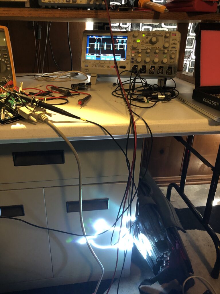
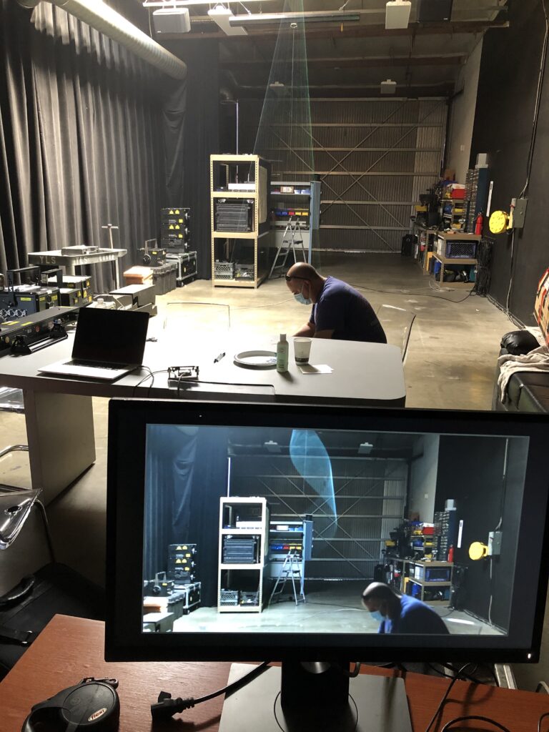
When I first got to YLS we plugged everything in to make sure I could run their projectors, etc. Surprisingly, everything came up fine. Steve at YLS has a reputation. His superpower appears to be destroying computers and electronics just by touching them. Or, on a good day, just looking at them. But fortune smiled on us today – or he was just distracted looking at his phone (see below). Anyway…
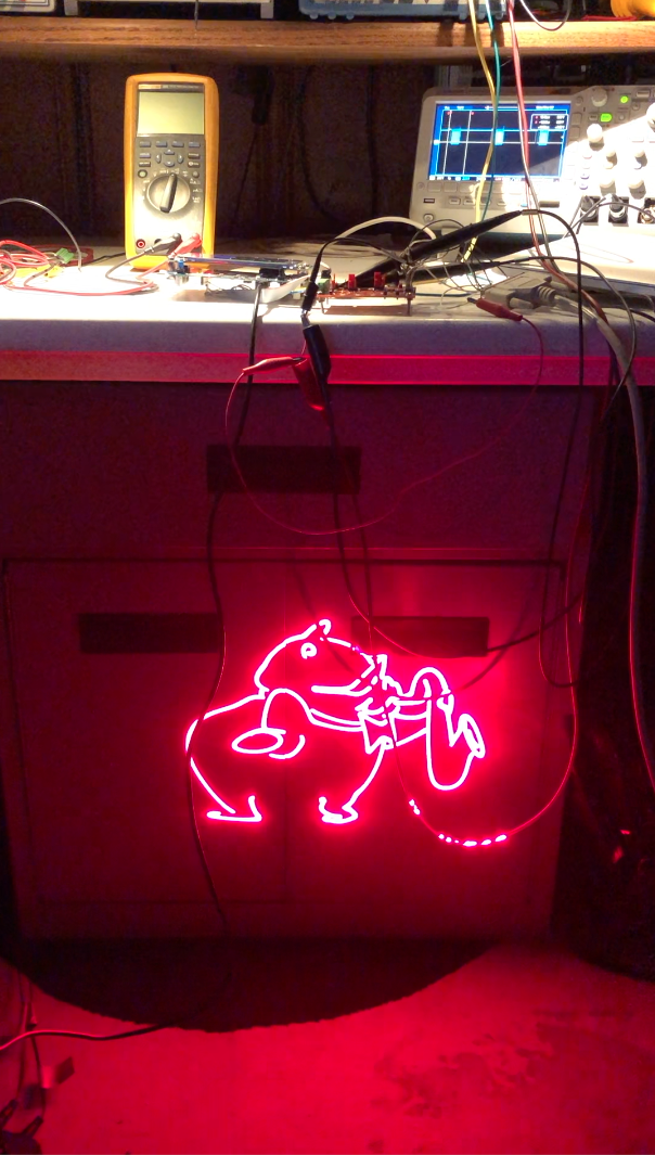
Next they showed me the interaction of the commercial scanning system they are using now with a rolling shudder. You could get the gist, there were some cool results on the monitor, but you couldn’t really dial in the effects or smoothly manipulate them. So we switched to my card and started with a simple circle. We had no problem freezing or smoothly reversing the first physics defying spiral on the monitor we tried:
We next confirmed that we could stop the movement in rolling shutter harmonics with other frames selected at random from other ILDA files ad at different camera shutter speeds.
Last we crudely tested one of the ideas that Marty at YLS has been thinking about for this technology – human interaction. We had Marty catch a virtual arial ribbon, hold it still for a few moments, then tap it in the other direction. As you can see above, even in a lit room, with a skylight no less, it is a pretty cool effect.
But we need to do one more piece. You could dial in some cool effects, manually winding and unwinding aliasing artifacts to exactly where you want them to start in space, then shoot a video of just that effect. But if you want to do multiple rolling shutter effects, or incorporate them into, say, the video wall at a live show, you need a way for the effects to come up in the right place, ready to go, every time. Basically, we need to synchronize to the start of each video frame in the camera.
I tried a quick hack with a cheap HDMI->VGA adapter, but that’s not going to get us where we need to be, so I’ll be digging in and doing a proper sync soon. Still, a fun few hours today. More soon!
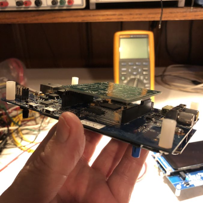
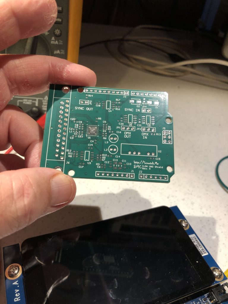
What can I say, waking up new hardware is always fun, particularly when it goes smoothly. I wasn’t quite sure if I really wanted to go with the Arduino ‘stackable shield’ connectors or not, so I had the CM (contract manufacturer) leave those and the DB-25 connector off the cards they assembled for me.
I started to panic slightly putting in the stackable Arduino style connectors. The hole size everyone seems to use is a bit snug. The connector doesn’t just drop in, you have to press and wiggle a little. The idea is to hold the pins well aligned for the board below and the board on top, but I made a note to increase the hole size slightly when I reorder boards.
First, the tolerance is a bit tight for an outside CM to easily assemble. Second, the little bastard drew blood. When one of the connectors did finally slide into its spot, I jabbed my finger.
Give me a boo-boo and vengeance will be mine!
Anyway, once the connectors were installed I next hooked 5V directly to the board and checked the onboard +/-9V supply, both with a meter and the scope. When those looked good I went ahead and installed the board on our ARM board.
You might recall from our schematic that the DAC channels are used a little differently than with the TI DAC eval board we first tested on. So I changed the code in scan.c to match, and checked the DB-25 output with the scope.
With X, Y, R, G, and B all working, I next initialized and tested the shutter and blanking lines with the scope. Again, no problem. Same with the 3 spare color channels. Eager to see things go, I finally plugged in the ILDA projector:
I’d been just using the red channel for most my testing and had forgotten how bright this projector is in white (it overwhelms my cell phone camera) and, damn, my lab chair is squeaky, but it is always gratifying when everything works as expected first time.
With the core functions out of the way, I next checked out the new features. Although they aren’t nearly complete, I created placeholder modules for both Sync and DMX to test those parts of the hardware.
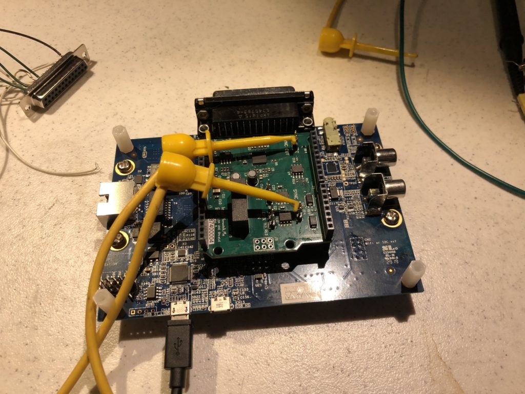
For sync, I just hooked OUT to IN with a jumper:
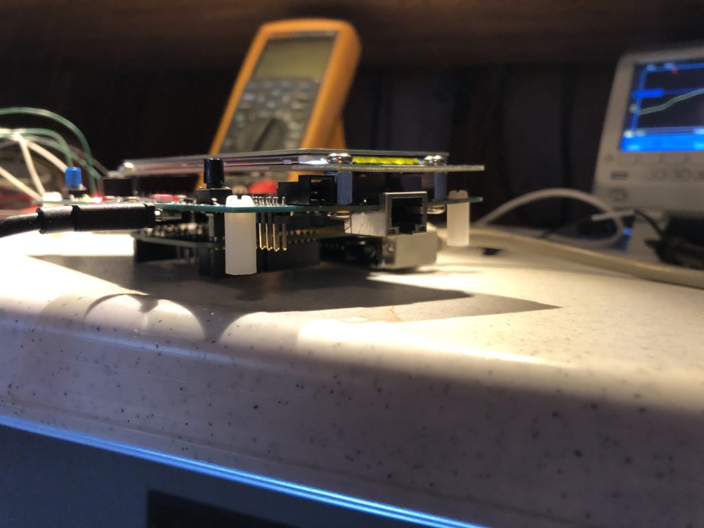
Then I toggled the OUT line in the firmware and reported what I read on the IN line using the debug trace function. DMX wakeup was similar, but it is a differential pair so I used two jumpers, as you can see at the picture at the top of this post.
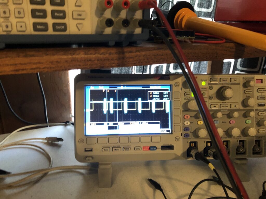
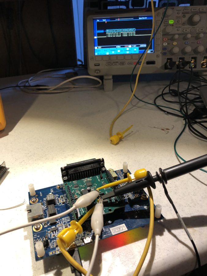
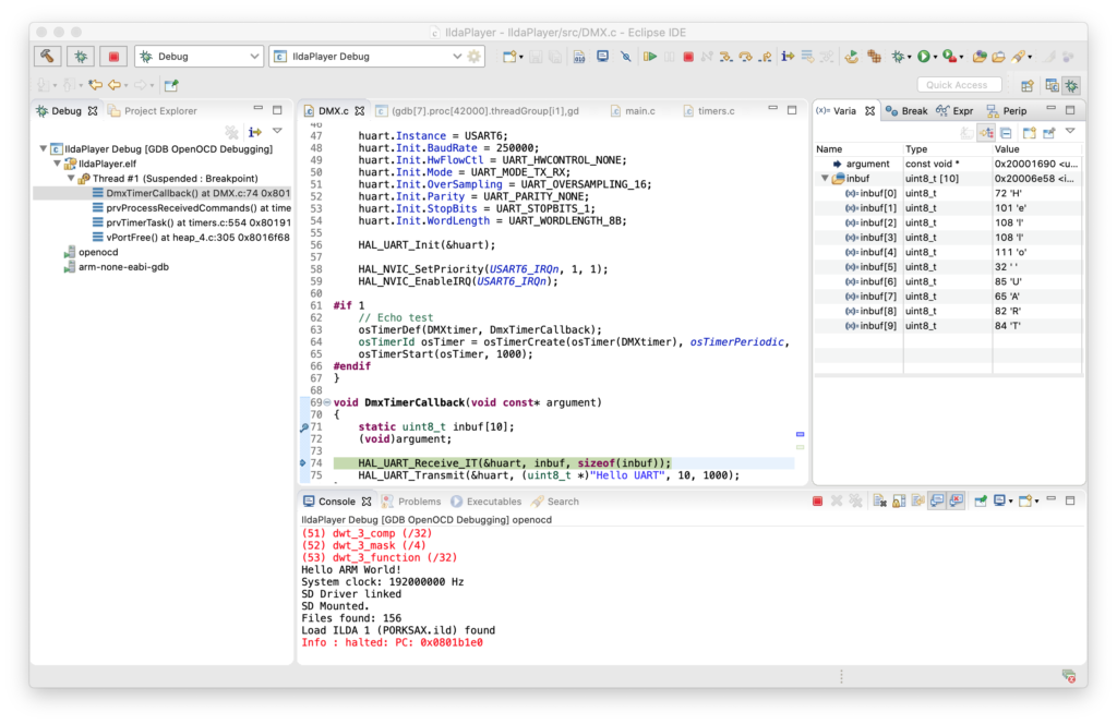
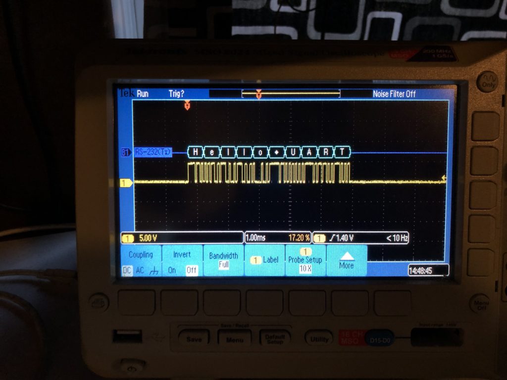
I’ll just say it. The ST HAL Library UART library code is utter crap. We’ll have to write something from scratch when we do DMX for real, but the ST code is good enough to test the DMX hardware functionality. I setup a FreeRTOS timer to send a test message via DMX once a second, then setup a break point to see that the message received matched what I sent at DMX’s 250kbit baud rate:
My oscilloscope has a nice RS-232/485 decoder, so I also used that to make sure both sides of the differential pair code be decoded at the expected baud rate and polarity, but I had to switch to a different baud rate than DMX standard. The scope doesn’t support 250kbit, so I just switched the firmware to the closest value the scope has for the test:
Last, I commented out the Sync and DMX test functions and pushed everything to the repo. I still need to pick up some longer standoffs from McMaster Carr so the assembly sits on legs, not our card:
And, at some point, I’ll want to get locking hardware for the DB-25 connector. But now that we have a solid controller module it is time to head to YLS Entertainment and take a first stab at the synced video effect!
Last post I promised to bring up the Ethernet connection on the board. Bringing up embedded ethernet connections is a bit like home improvement on an older home. At the start it seems like smooth sailing, then you hit a small snag, open a tiny hole in a wall, peek inside and… BAM. Hours later you are wishing you had just tossed a throw rug and some spackle on the original problem and prayed no one would notice. This was no exception, though I’ve been through the process enough times that it really only ended up being a few hours of work.
It all starts with the low level network driver. Low level Ethernet peripherals are almost always spectacularly complex and inevitably come with thin, crappy, documentation. If the chip vendor has done a sample driver, trust me, that’s really where you want to start.
I built and loaded one of the ST provided networking samples with IAR. Once it passed some basic ethernet stress tests, I was ready to port that driver over to the free Eclipse/GCC compiler combo we are using.
But first I had to make a decision. The driver, which is in a file called “ethernetif.c”, is structured to rely on some POSIX style operating system services. Honestly, I was really hoping to avoid any type of OS or RTOS. We already have a simple scheduler and I have good stand-ins for critical sections and semaphores as well. But I took a quick look at the USB stack from ST we will also eventually want to use and it’s a similar situation, so I decided to just go with the flow.
So, before porting the network stack, I first ported over FreeRTOS. It’s not terrible and the port was quick and painless. Still, I was pretty quickly reminded why I like to keep firmware lean and mean whenever possible.
Next step I moved the driver over and just tried stress testing it at a low level with Ethernet Frames. Since I had already done this once, I was just going through the motions not really expecting a problem but, BAM. The ported driver worked in simple cases, but messed up in stress testing.
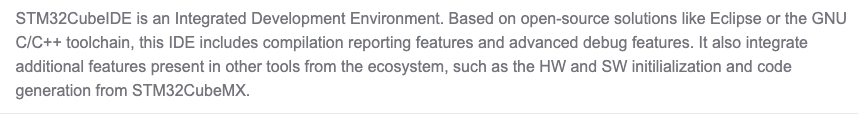
To cut a long story short, it all boils down to the GCC compiler not really being well supported by ST, even though they offer their own version of Eclipse/GCC called STM32CubeIDE:
GCC support is clearly a lot weaker than for the commercial Keil and IAR tools. For example… The Ethernet peripheral built into our MCU can be pointed to different SRAM locations for data operations. But this more advanced STM32F7xx Cortex M7 core also has data and instruction caches for a performance boost. The problem is we don’t want memory we have assigned to the Ethernet peripheral to use caching. Sort of like declaring a variable “volatile” in C/C++, we want to make sure we examine the real memory space, not a cached copy, every time.
No problem, the chip has a MPU or “memory protection unit” built in as well. We can use it to make part of the memory interact with the caches as we wish, and ST did just this in their sample:
static void MPU_Config(void)
{
  MPU_Region_InitTypeDef MPU_InitStruct;

  /* Disable the MPU */
  HAL_MPU_Disable();

  /* Configure the MPU as Normal Non Cacheable for Ethernet Buffers in the SRAM2 */
  MPU_InitStruct.Enable = MPU_REGION_ENABLE;
  MPU_InitStruct.BaseAddress = 0x2007C000;
  MPU_InitStruct.Size = MPU_REGION_SIZE_16KB;
  MPU_InitStruct.AccessPermission = MPU_REGION_FULL_ACCESS;
  MPU_InitStruct.IsBufferable = MPU_ACCESS_NOT_BUFFERABLE;
  MPU_InitStruct.IsCacheable = MPU_ACCESS_NOT_CACHEABLE;
  MPU_InitStruct.IsShareable = MPU_ACCESS_SHAREABLE;
  MPU_InitStruct.Number = MPU_REGION_NUMBER0;
  MPU_InitStruct.TypeExtField = MPU_TEX_LEVEL1;
  MPU_InitStruct.SubRegionDisable = 0x00;
  MPU_InitStruct.DisableExec = MPU_INSTRUCTION_ACCESS_ENABLE;

  HAL_MPU_ConfigRegion(&MPU_InitStruct);

  /* Configure the MPU as Device for Ethernet Descriptors in the SRAM2 */
  MPU_InitStruct.Enable = MPU_REGION_ENABLE;
  MPU_InitStruct.BaseAddress = 0x2007C000;
  MPU_InitStruct.Size = MPU_REGION_SIZE_256B;
  MPU_InitStruct.AccessPermission = MPU_REGION_FULL_ACCESS;
  MPU_InitStruct.IsBufferable = MPU_ACCESS_BUFFERABLE;
  MPU_InitStruct.IsCacheable = MPU_ACCESS_NOT_CACHEABLE;
  MPU_InitStruct.IsShareable = MPU_ACCESS_SHAREABLE;
  MPU_InitStruct.Number = MPU_REGION_NUMBER1;
  MPU_InitStruct.TypeExtField = MPU_TEX_LEVEL0;
  MPU_InitStruct.SubRegionDisable = 0x00;
  MPU_InitStruct.DisableExec = MPU_INSTRUCTION_ACCESS_ENABLE;

  HAL_MPU_ConfigRegion(&MPU_InitStruct);

  /* Enable the MPU */
  HAL_MPU_Enable(MPU_PRIVILEGED_DEFAULT);
}
At first glance it’s a little weird that in this code one memory region completely overlaps the other, but it makes sense if you read through the MCU documentation which is, of course, hard to find. Normally the go-to place for info on STM32Fxxx chip peripherals is something called the “Reference Manual”, but the version for our chip has no mention of an MPU anywhere in the text. The datasheet for our chip only states that the MPU exists, but gives no details.
The two places that explain it are an app note, and the Programmer’s Reference for the core. If you wade through that info, the two blocks above make sense. But even without digging into all the details, we can see that we want the memory we assign to the Ethernet peripheral to be in the 16K around 0x2007C000. If we look at their driver code, this appears to be the case:
Four memory buffers are allocated and, depending on which compiler is used, are forced to 0x2007C000 – 0x2007D8D0 different, compiler specific ways. For Keil and IAR, the addresses are called out as absolutes. For GCC, the GNU compiler we are using, placing something at a specific memory location is done indirectly. Basically allocations can be expressly put in a named “section” and then a loader file instructs the GCC linker to put sections in defined memory spaces. Enter the ST provided sample loader file:
If you look back at the GCC specific assignments in the driver code above you will see that three of the four sections used in the driver source code do not exist in the matching loader file. “.RxDecripSection” has a typo (should be .RxDescripSection, with an added s), and .RxarraySection and .TxarraySection are nowhere to be found. They should be .RxBUF and .TxBUF. Only our TX Descriptors were in memory at the correct location with the desired attributes, hence our results. It worked well enough to pass a few seconds of testing at ST, but died under stress testing here.
With that changing-the-vanity-light-lead-to-resealing-the-pan-in-the-shower adventure out of the way, the rest of basic network support went quickly. The basic stack is LwIP (Light Weight IP). A stack originally developed by Adam Dunkels. Back in the dark ages I contributed a few enhancements and fixes, so I have no reservations using it here.
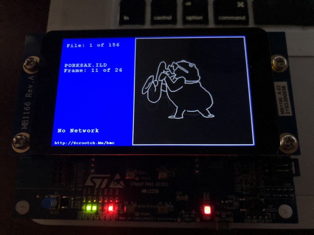
I brought the stack up in two stages. First, I just initialized TCP and bound the network driver to the stack. If there is no network connection detected, the display now tells you so:
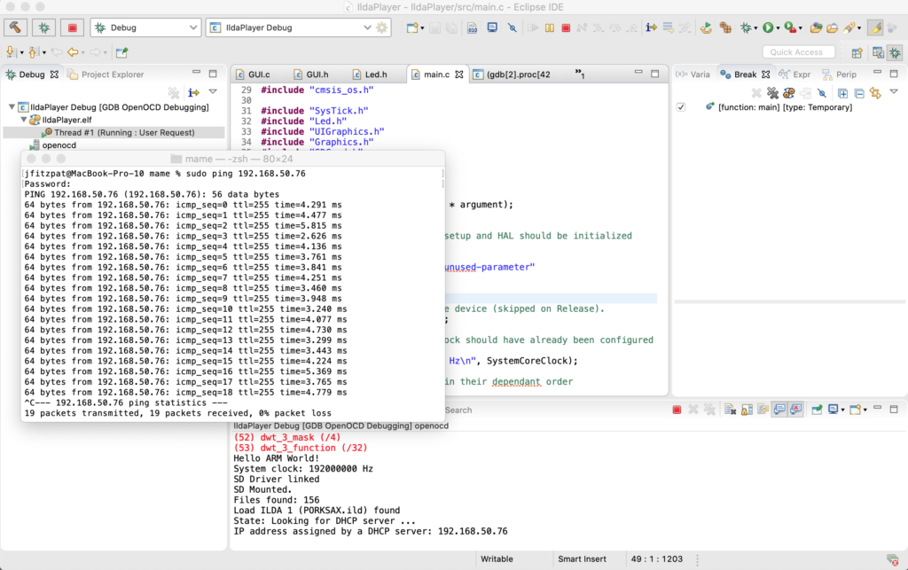
If a connection is found, you can see the card initially having no IP address, and then getting one from a DHCP server:
Once the card has an address you can ‘ping’ it from a computer on the network:
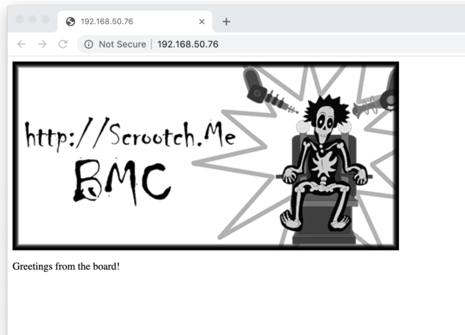
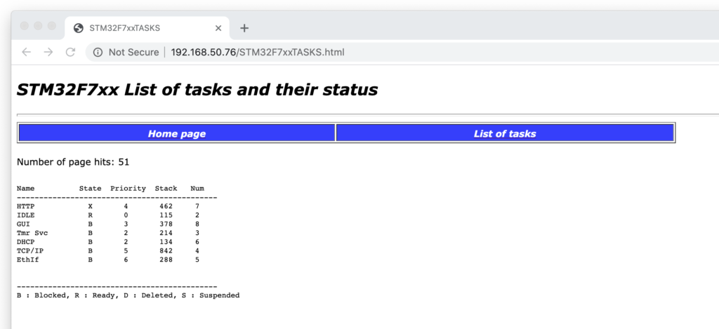
For the second test I threw in a simple HTTP server sample. In addition to the dirt simple fixed page you can see at the top of this post, I also threw in a dynamic web page from the ST.com sample:
This page auto-refreshes and shows the current FreeRTOS tasks and their status. I cranked the refresh rate up and used it to confirm there is no impact on our interrupt driven scanning.
For reasons I will explain in another post, we won’t be using the HTTP protocol to control our projector. I also have a tick list for networking I will still have to do at some point (ex. read network settings from the SD card, handle all the hot-patching cases, etc.), but what you see here is pushed.
Our assembled PCBs are already on their way back to me so, next stop, hardware wakeup!
As promised, I had a little time on Friday to work on the system. In the back of my mind I was thinking I would bring up Ethernet because we are close to the point where we are going to want to control the system from a computer. But I spent the time working out two very different forms of the same basic synchronization vs. visual perception problem.
I started with a little house keeping. Before, the touch screen would only let you drag around a little square, but I changed it so you can scroll through ILDA files and their frames and turn automatic animation playback of a given file on and off.
This brought up the first sync issue, which I expected. When manually jumping through frames in response to display taps, or automatically switching frames at a constant time rate, like 10 Hz, visual glitches appear in the laser scanning. This is because we were not yet synchronizing by frame. Imagine we stop at some random point in a frame, which is a visible dot. Then we leap to the blanked dot somewhere else on the screen that starts the next frame of the animation. There is a little ‘tail’ where we can see the laser jumping at it races to the start of the next frame.
For now I fixed this with the basic solution – frames now always finish scanning before we switch to a new frame. This is something we are going to want to do a lot moving forward, like when we are moving or rotating an image on the screen.
When we start using the same scanner for multiple images the problem gets a bit more sophisticated but, for now, this gives us very smooth playback of animations (the rolling shutter doesn’t really do this sax playing pig justice):
This brings up the second sync problem. I expected the frame display on the LCD to be a little flickery. My simple routine turned off a layer on the LTCD controller, cleared the memory to transparent, drew the new frame and updated text, then turned the layer back on. So that last text and image disappeared briefly while the new one is being rendered. But playing frames over and over, we get occasional full on screen glitches as well:
If you view the video above full screen you will see that the text is a little flickery updating but every once in awhile we get a white flash that fills much of the screen. This isn’t related to touch or user interaction. It will happen if we just let an animation play.
We have two onboard peripherals running, the LTDC controller, which is reading two screen size blocks of SDRAM (one for each ‘layer’), and blending them together into a pixel stream for an LCD display, and the DSI peripheral, which converts that pixel stream into a DSI interface compatible data stream. The flashing is because I was not synchronizing turning the layer off and back on with vertical sync. That is, much like we got a glitch when I didn’t completely scan each ILDA frame, we sometimes get a glitch when we turn an LTDC layer off and on in the middle of a LCD frame being displayed.
There is a kludgy way I could have hacked around the flash, but we are rapidly hitting the limits of my simplistic drawing code anyway, so I decided to just bite the bullet and put something more sophisticated in now. There are two common techniques in embedded systems like ours.
One, “partial refresh”, involves splitting the screen into quadrants and updating one part of the screen buffer while another part is being transmitted to the display. This can be a great way to conserve memory, since you can get by with a single display buffer, but it makes rendering a real time task – that is, you are on a fairly strict timeline to get things updated in SDRAM if you want to avoid visible tears and glitches.
Since memory isn’t a problem for us and I’d rather make the graphical interface a “reasonable time task” – something we want to complete fairly quickly, but nothing will glitch or freak out if we get really busy doing something else and fall behind on display once in awhile. So I opted to go with a technique called “Page Flipping”:
The graphic above is stolen from an Oracle Java Tutorial and it is hopefully pretty self explanatory. I setup two screen buffers. At any point in time, one is for drawing the next thing we want to display, the other is being actively scanned on the LCD. When we are ready to flip, we change the memory pointer for the LTDC layer at line 0 (basically vertical sync). At that point, the buffers’ roles are switched, or ‘flipped’.
Getting two buffers and page flipping setup was pretty quick and straightforward, but that left me without any usable graphics primitives. The samples from ST are all tethered to layers already assigned to the LTDC peripheral. I had to port the functions we’re using to a new module called Graphics.c and change them so they can be directed to any random memory buffer. There is a little additional optimization that I would like to do, but the results are already a pretty significant improvement:
As always, everything is in the git repo. And, yes, just having to know where to tap is a terrible user interface, but we’ll get to that! Next stop, bringing up a network interface…
In our last session we got the display up and running. I got a chunk of time both Sunday and Monday night to add a bit more.
First, I did a little house cleaning. I found that I was fixing quite a few bugs in the “HAL” peripheral drivers from ST.com, so I checked and found that the Eclipse templates we used to frame in the project are a little out of date. ST has a version from February 2020 you can download as part of the STM32F7 Cube MCU Package here. The release notes list some of the bugs I already fixed, so updated the files in our project and tweaked the API calls we are using that have changed.
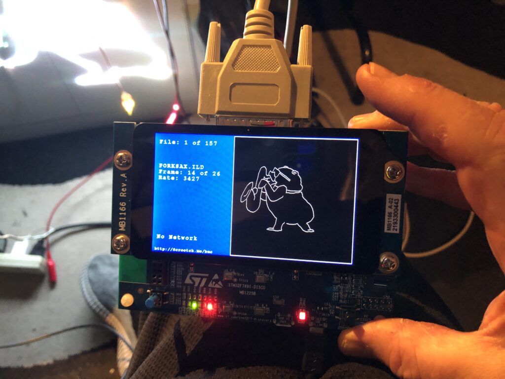
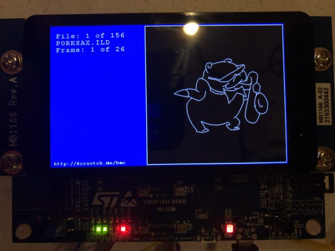
With that out of the way I brought up a the MicroSD card slot and a FAT file system. I actually wrote a nice file system for another project, but I’d have to check with the copyright holder to use it here, so I stuck with the one ST uses in their samples, FatFs, which is from here. None of the ST examples I could find used long file names, and there were some compilation and driver problems when I first set that option in the fs_conf.h, but nothing too hairy. I threw 150 or so ILDA files on a MicroSD card and, as you can see, filenames longer than the old DOS 8.3 (ex. CanadaFlag.ild) work fine:
Next I brought up the capacitive touch display, which relies on a FT6x06 chip from Focal Tech. The datasheet is here. It’s cooler than I expected, and two contact detection works well, so we’ll try to do some gestures for control soon. But for now I just have a cursor you can drag around the screen.
With a display, data storage, and touch input working, I started to frame in a better sample in earnest. I put together an ILDA file loader that normalizes all files into the “ILDA Format 4” (3D, true color) and caches them into SDRAM for scanning.
I then updated the simple scan code I used for testing the DAC so that it is using the cached data and ILDA_FORMAT_4 structure and can be pointed to different frames. Last, but not least, I added a simple frame renderer for the LCD so we can see what is going on.
The function supposedly handles color, though I have very very colorized ILDA files to test:
And those are all crap. When we get around to an editing tool we should colorize all these old graphics from LaserMedia’s early 1980’s Devil Went Down to Georgia module we did for a laser/fireworks show at the racist mother ship, Stone Mountain. Troubled context not withstanding, it remains one of the best laser graphics presentations I have ever seen, in no small part because Disney was laying off animators at the time:
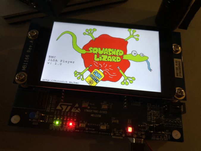
Enough nostalgia. At this point, we have a card that:
Shows a splash screen
Scans the installed SD Card for all available ILDA files in a folder named “Graphics”
Loads all the frames from the first one into SDRAM
Starts scanning the first frame
To show that touch input is working, you can also touch the screen and drag around a little cursor square:
Yes, it would be nice if I’d wired touch up to select files and frames. And yes, after having gone to the trouble of supporting long file names I still put up DOS 8.3 names on the display because I haven’t written a decent font manager yet. But my day job has been a bit busy lately (sneaking this post in during a lunch break). Still, we have quite a bit working. As always, you can pull the code directly from the git repo, but it is worth covering the scan code just a bit.
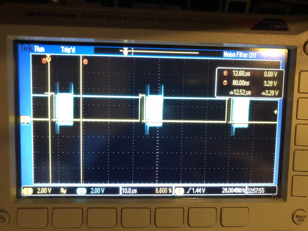
The first thing worth noting is how /CS, or “chip select” is handled for our DAC. You can see it in this scope trace. Yellow is chip select, blue is SPI clock:
The /CS line only turns off for short intervals that match our scan rate. This is intentional. We are writing all 8 DACs every time. The outputs take effect when the /CS line goes high, so that is the first thing we do each time interrupt. This synchronizes our DAC value changes very tightly to a very stable clock – something we will want for our intended video effect.
The interrupt handler next calculates all the new DAC values, asserts /CS, and starts transmitting over SPI. That is a DMA driven transfer, so the interrupt handler returns before the SPI clocking even starts, freezing up the processor to do other stuff, like ethernet, USB, DMX, etc. As it is, we are fitting very comfortably in the 28 kHz scan rate time windows. The vertical cursors show what a 60 kHz window (the fastest scanners I could find) would be and, again, this should be no problem, particularly since we are running a lot of inefficient HAL code in the handler. With that in mind, even 80 kHz looks pretty obtainable:
But if we want to scan any faster, say 100 kHz, we’ll need to mod the base card so we can do SPI with an onboard controller on the STM32F769’s other, faster, peripheral bus. As we discussed when we sketched the card out, the lines on the Arduino expansion connector can only go 25 MHz, half the speed that the DAC can accept data.
Another odd thing you might see in the code is this, in the interrupt handler:
		int32_t val;
		val = pntData[curPoint].x.w;
		val += 32768;
		DacOut[1] = val >> 8;
		DacOut[2] = val & 0xFF;

		val = pntData[curPoint].y.w;
		val += 32768;
		DacOut[5] = val >> 8;
		DacOut[6] = val & 0xFF;

		int16_t idx;
		if (CurrentFrame->numPoints > 4)
		{
			idx = curPoint - 4;
			if (idx < 0)
				idx += CurrentFrame->numPoints;
		}
		else
			idx = curPoint;

		if (pntData[idx].status & 0x40)
			DacOut[9] = DacOut[10] = 0;
		else
			DacOut[9] = DacOut[10] = 0xFF;
X and Y handling isn’t optimized (we’ll get to it!) but pretty clear. The data is fetched, shifted for a unipolar DAC, then put in the message in “big endian” order. But blanking information is then shifted to come from 4 points earlier in the scan. This is because most these graphics are old. They come from a time when blanking (laser invisible) was done with a 3rd scanner, or galvanometer. The diode lasers in the projector I am using are faster.
When we scan these images at 14 kHz (what they were originally created at), we need to shift about 2 scan intervals later to get the intended blanking effect. Up at 28 kHz, it becomes 4 scan intervals (what the code is doing above).
From what I can tell, there are really three generations of laser graphics content floating around. Old content like this, created for mechanical blanking and color. Brand new content, created for diode laser blanking and color control, which is faster, and a generation in between, that used acousto optical defection, or modulation. This technology appears to have largely disappeared because the diode technology is cheaper and has less energy loss, but it was faster. So graphics created for it would generally need blanking and color changes shifted in the opposite direction from what we are doing here.
The moral of all this is we are going to want to generalize this mechanism and expose control of it so that people can easily utilize older graphics.
Lunch break is over, but I’m hoping to see our PCBs from FedEx today and get them sent to the contract manufacturer tomorrow. I should be able to get another chunk of time to move the system forward again soon.
Now that we have a simple skeleton, it’s time to bring up some peripherals. It’s probably not the most important, but of course we want to start with the LED/capacitive touch display. It’s shiny!
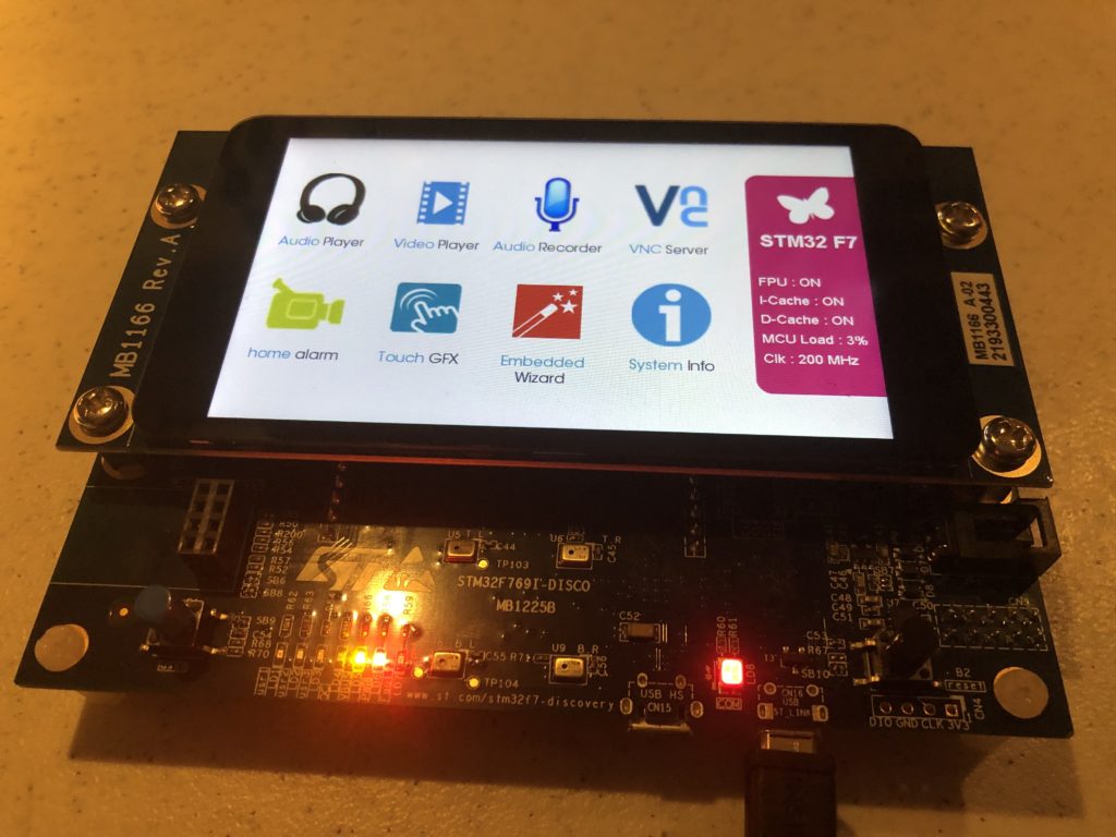
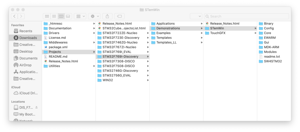
A good place to start when you are trying to figure out how to do or use something in software is often to look at a sample that already does what you want. Our evaluation board originally came with a really nice demo already installed:
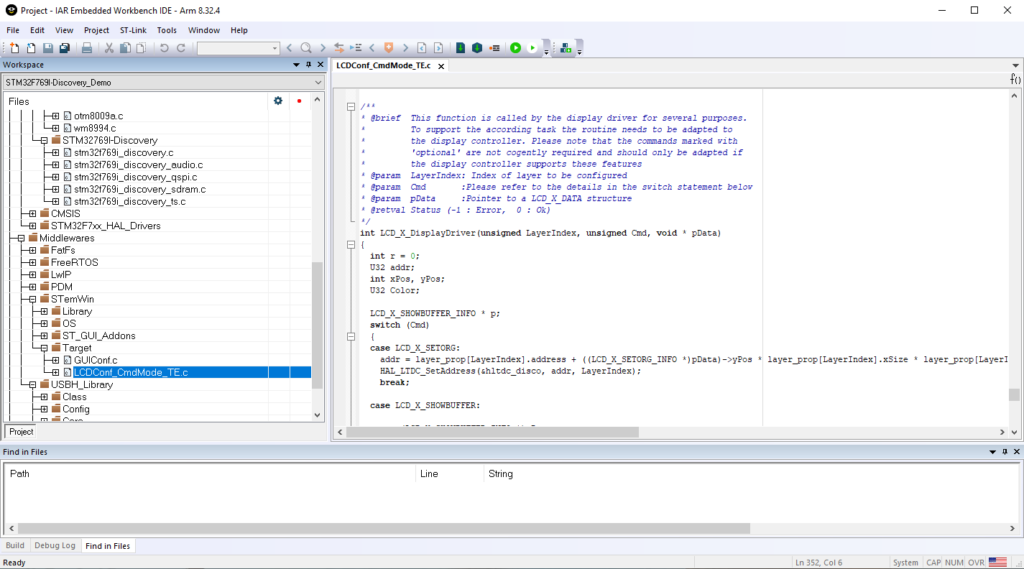
But if we look at this project (I’m cheating and using the commercial IAR tools and the project folder (EWARM) that ST included), we hit a few snags:
The LCD isn’t supported at a clean, stand alone driver level in this code. Those (audio, qspi, sdram, ts) are in the folderSTM32769I-Discovery. LCD support is in “LCDConf_CmdMode_TE.c” buried in a folder under Middlewares / STemWin.
STemWin is a version of emWin that ST licensed and distributes in library form. The C file above is a display device driver written to be compatible with STemWin/emWin.
I’m sure that STemWin is fine, but I really don’t like relying on object only libraries. Among other things it really hampers your ability to track down and fix bugs. So, we aren’t going to use STemWin and we sure as hell aren’t going to give a German company $12,000 for software I can’t share as source with you!
On top of everything else, for reasons that I’ll explain below, the demo won’t build and run quite as expected from the IAR debugger for us to investigate what is called and in what order. Still, being familiar with writing device drivers and the ST peripherals involved, I could cobble together a stand alone driver from the example, but we don’t have to:
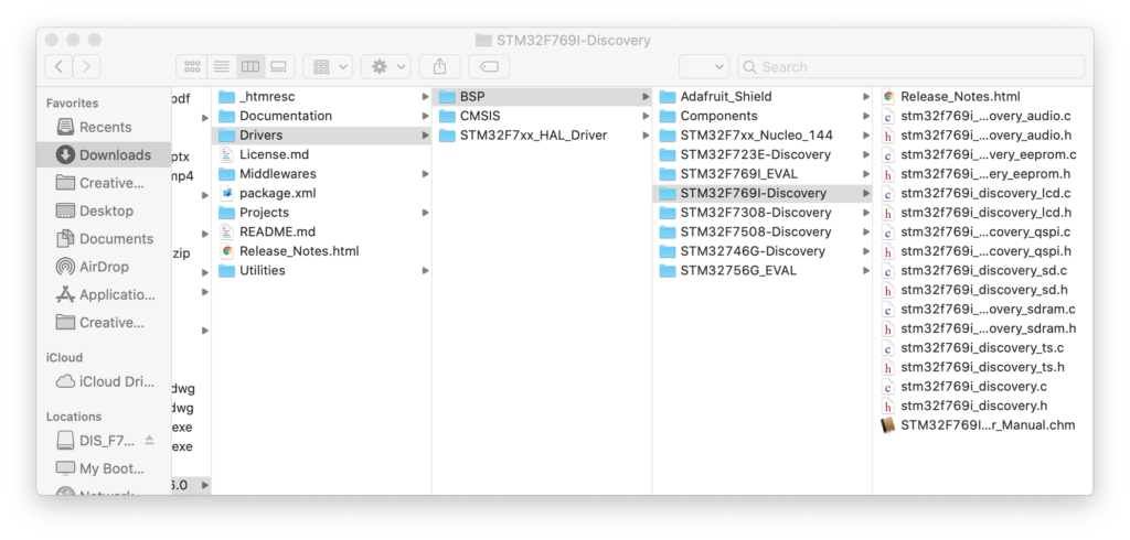
In the same package as the demo source is a folder called drivers with a subfolder for “BSP” (presumably ‘board specific peripherals’). If we select our eval board we can find a .c and .h file for the LCD display.
We can literally drag these files to our project in Eclipse and Eclipse will offer to make a local copy and add them to our project for compilation. But, we will find that there are usually the same few steps required to make this work.
Copy the desired ST driver over
Try to compile
Use the errors to find the additional driver(s)/file(s) you need to copy over
Flatten the include paths hard coded into ST provided files
Repeat 2-4 until you only get linker errors
Enable the missing parts of HAL library to get rid of the linker errors
Go back and tweak code and/or use pragmas to get rid of any warnings
The LCD driver is a good example of this. It relies on another BSP driver for SDRAM, some component specific drivers (ex. otm8009a.c, adv7533.c, etc.) and a simple font system with the fonts each in an individual .c file. A number of these files use complex relative include directives like this:
The ../../../Utilities/Fonts stuff is hard coded to the complex folder structure of the STM32-Cube package. We don’t have that. Including .c files for indirect compilation (what’s going on with the .c files) is a technique to be used with care. We won’t use that here, so I changed this to:
/* Includes ------------------------------------------------------------------*/
#include "stm32f769i_discovery_lcd.h"
#include "fonts.h"
// .c font files used are just added and compiled to the project normally
// so no reason to include here
//#include "../../../Utilities/Fonts/font24.c"
//#include "../../../Utilities/Fonts/font20.c"
//#include "../../../Utilities/Fonts/font16.c"
//#include "../../../Utilities/Fonts/font12.c"
//#include "../../../Utilities/Fonts/font8.c"
Once all the pieces are in and compiling correctly, we start getting linker errors for HAL library functions that can’t be found. That is because, although the entire HAL library was included in our project when we created it, a bunch of the .c files were set to be excluded from compilation by default.
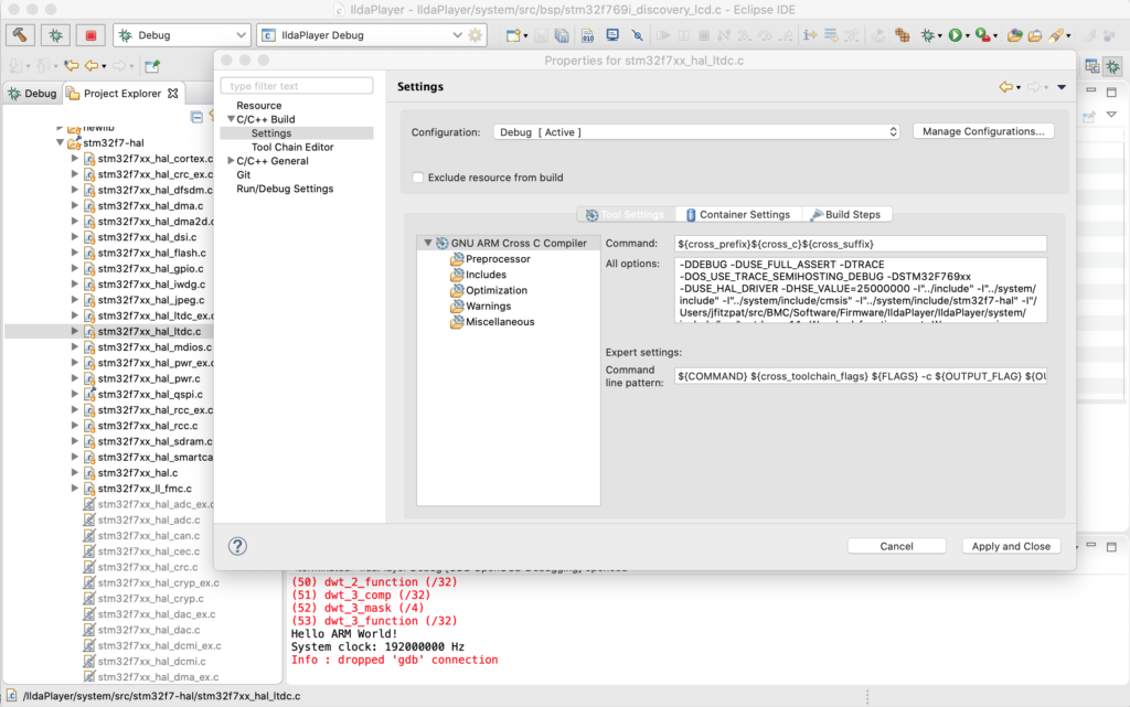
To fix this we find the needed file, which is in the tree but greyed out, right click on it, and select “Properties”:
Under C/C++ Build / Settings make sure that the “Exclude resource from build” checkbox is unchecked and the needed HAL file will now be compiled with our project.
Eliminating all remaining warnings is just my thing. If you don’t, how will you know that something you just pulled from a git repo compiled correctly? In this case a number of the files throw warnings for unused variables, which I eliminated with #pragma statements, for example:
#pragma GCC diagnostic push
#pragma GCC diagnostic ignored "-Wunused-parameter"

__weak void DSI_IO_WriteCmd(uint32_t NbrParams, uint8_t *pParams)
{
  /* NOTE : This function Should not be modified, when it is needed,
            the DSI_IO_WriteCmd could be implemented in the user file
   */
}

#pragma GCC diagnostic pop
Digging deeper and understanding the hardware and peripherals involved with the LCD display is well worth doing. The primary connection is something called DSI (digital serial interface), a standard from MIPI (Mobile Industry Processor Interface Alliance). ST has an app-note on their integrated DSI host controller here.
In addition to the DSI communication peripheral, the LCD driver we are using utilizes two other peripherals built into the MCU. LTDC, an LCD-TFT display controller, and DMA2D, a special direct memory access controller for common operations in 2D graphics (like converting between color spaces). You can read about both these peripherals in the Reference Manual for our MCU.
There are some differences between the driver in the STemWin demo above and this standalone driver that we will be considering a little down the road, like the tradeoff between color spaces used and SDRAM spaced needed, but for now let’s just make something happen!
With everything compiling we still need to initialize and use the driver, so I made another module called Display.c. To start, we can make our display_Init() look like this:
void display_Init()
{
// Initialize in Video Burst Mode, bail if we rail
if (BSP_LCD_Init() != LCD_OK)
return;
// Initialize our background layer, using SDRAM
BSP_LCD_LayerDefaultInit(LTDC_ACTIVE_LAYER_BACKGROUND, LCD_FB_START_ADDRESS);
// Select and clear to black
BSP_LCD_SelectLayer(LTDC_ACTIVE_LAYER_BACKGROUND);
BSP_LCD_Clear(LCD_COLOR_BLACK);
// Now do the same for the foreground layer, but make white
BSP_LCD_LayerDefaultInit(LTDC_ACTIVE_LAYER_FOREGROUND, LCD_BG_LAYER_ADDRESS);
BSP_LCD_SelectLayer(LTDC_ACTIVE_LAYER_FOREGROUND);
BSP_LCD_Clear(LCD_COLOR_WHITE);
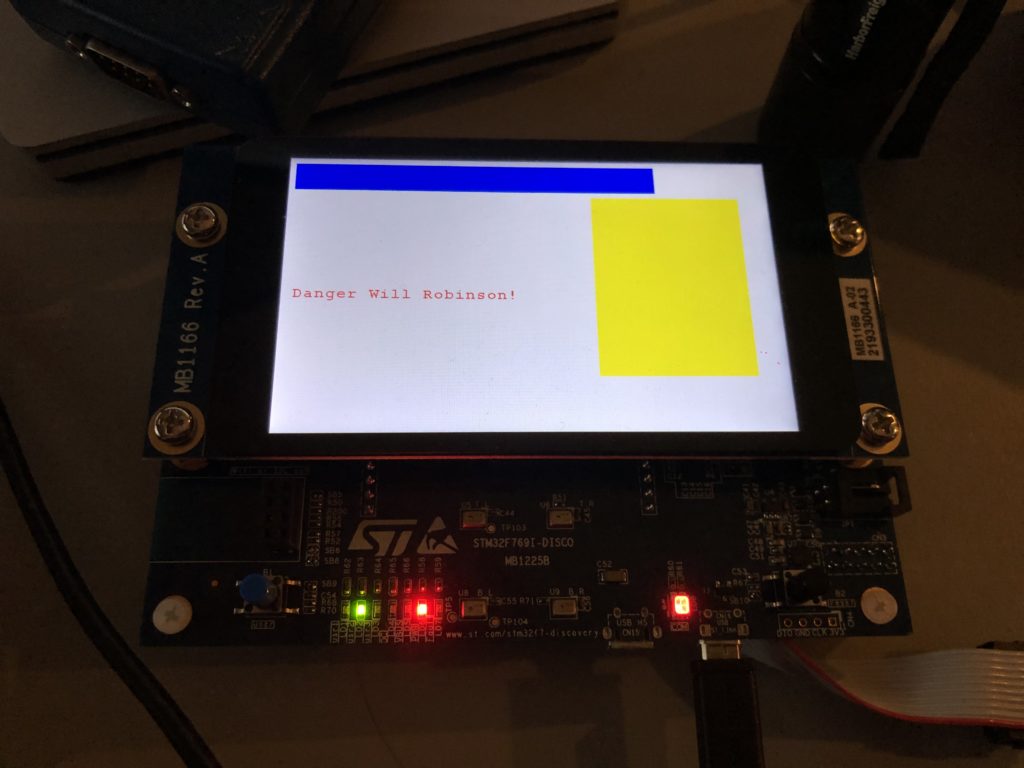
// Let's throw in a string
BSP_LCD_SetTextColor(LCD_COLOR_RED);
BSP_LCD_DisplayStringAtLine(10, (uint8_t *)" Danger Will Robinson!");
// And a couple of rectangles
BSP_LCD_SetTextColor(LCD_COLOR_BLUE);
BSP_LCD_FillRect(10, 10, 600, 50);
BSP_LCD_SetTextColor(LCD_COLOR_YELLOW);
BSP_LCD_FillRect(500, 70, 250, 320);
// Adjust brightness
// BSP_LCD_SetBrightness(100);
// Background transparent, foreground opaque
BSP_LCD_SetTransparency(LTDC_ACTIVE_LAYER_BACKGROUND, 0);
BSP_LCD_SetTransparency(LTDC_ACTIVE_LAYER_FOREGROUND, 255);
}
BSP_LCD_Init() invokes the ST provided driver to do most the work, but we have to do a few more things, the big one being to initialize our two “layers”, foreground and background. These have to be setup to use SDRAM memory. That’s our only choice because of the math.
The display is 800 x 480 pixels. We are initialized so that our layers are all 32 bit. That is, for each pixel there is a byte each for Red, Green, Blue, and Alpha (transparency). 800 x 480 x 4 = 1,536,000 bytes. Two buffers that size would be 3,072,000. Our MCU has 512k of onboard SRAM. That’s not big enough to hold one layer buffer, let alone two! Fortunately, our eval board has 16M of SDRAM (SDRAM is like DRAM, but ‘synchronized’ to the CPU’s clock so it is more efficient to access).
With SDRAM initialized and our layers set to use it, we can do a few low level graphics operations and… it works!
Clearly, at some point we are going to have to do a better font engine but, for now, we could build up a pretty nice UI just using primitive graphic routines (provided we get help from someone artistically inclined). Still, chances are, we are going to want to be able to display at least some bitmap graphics.
Let’s start with a splash screen. We’ve already established that I’m not very artistically inclined. But, as luck would have it, Spotify Stations played this just as I began scrambling for a bitmap to try:
And the image tickled me. A quick web search for the Aussie band turned up a higher res version of the image, so I used Photoshop to make a 800×480 16 bit (RGB565) version:
Then I used a tool we’ll revisit in another post to turn the .bmp file into C source code that can be compiled as data in flash memory and put it in a new module called UIGraphics.c:
It is declared “const” so it will go into the MCU flash memory (read only). With the bitmap now memory accessible I next changed the drawing portion of display_Init() to this:
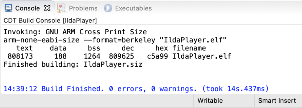
As you can see in the image at the top of the post, it works great, but we have another math problem looming. If we check our compiled code size, which is reported after each build, we’ll see:
The flash part is “text” (for nerd historical reasons, ask me sometime when I’m drinking). We are pushing 800k with one image! This makes sense, 800x480x2 = 768,000. But we only have 2M (2048k) total in the MCU. There are some tricks we can (and likely eventually will) use to get this flash down. For example, we could compress the image resources and decompress them into our SDRAM at runtime when we want to use them. But still, graphics could use our on board flash up in a hurry.
As luck would have it, our eval board has 64M of external flash hooked to our MCU. The chip is a “QSPI flash memory”. Again, ST has a presentation on the QSPI interface here. But QSPI is basically an upscale from SPI, the interface we already used to communicate with a DAC. It uses 4 lines to carry data instead of 1 so it is faster. In addition, the controller on the MCU has a memory mapped mode.
This means that you can tell the MCU how to do serial QSPI read commands and it will make the QSPI memory seem like conventional memory you can access directly. ST was kind enough to include a QSPI driver for the chip on our board with the STM32 Cube samples. Once we have ported the driver to our code with the normal steps we used for the LCD driver above, we can change our uiGraphic_Init() function to this:
The QSPI flash will now ‘look’ like 64M of regular flash memory starting at and address of 0x90000000. To move our bitmap there we have to do two more things. First, we have to edit the linker file mem.ld in our project:
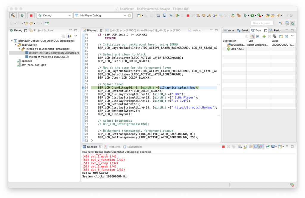
The file had for placeholders for external memory already defined. I just changed EXTMEMB0 to an origin of 0x90000000 and set a length of 64M instead of 0. Second, we have to tell the compiler where to put our bitmap data with a “section directive” in our C code:
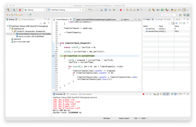
Now if we stop with the debugger and put a watch on uiGraphics_splash_bmp (top right) we can see that the code does now expect the bitmap data to be at 0x90000000:
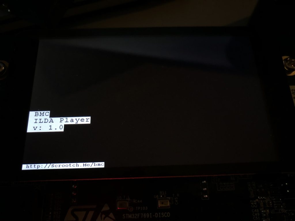
But when we allow the code to continue, our text still displays, but the bitmap is gone:
There is an obvious Catch-22. We have to have some code running on our MCU that properly configures the QSPI peripheral in order to write to the external flash chip. The OpenOCD setup we are using only knows how to write to the flash and ram on the MCU itself. This is why the STemWin demo did not run as expected when compiled with the IAR tools above. The IAR tool suite also didn’t know how to load graphics in external flash either and the demo relies on the same technique we are using.
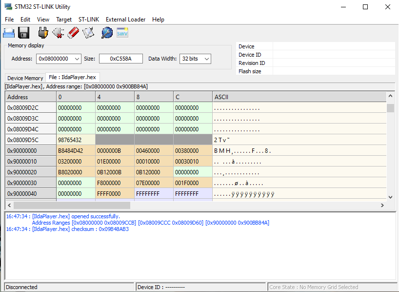
We could write our own custom loader, but we don’t have to. ST offers some free utilities for ST-Link, including this one. We can load the .hex file generated from our compile with the tool and see that our bitmap data is at the desired address:
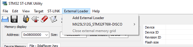
We can then use the External Loader menu to add “MX25L512G_STM32F769I-DISCO”, a flash loader ST developed just for our eval board:
Then, when we select Target / Program, the tool does all the dirty work. It puts a small loader in the MCU’s RAM, loads the QSPI flash memory with the data we want to program there using it, and programs the MCU flash normally. Cycle power and boom! Our bitmap is back, this time loaded from QSPI flash.
Note, we only need to use the tool to load the external QSPI flash chip. Once any expected resources are flashed there we can keep programming and debugging as from the Eclipse IDE as before. As always, the code above can all be pulled from the git repo.
Keep them doggies coding… Sorry, inside joke. When I was working with a team developing one of the first direct-to-disk audio editing systems back in the late 80’s, all my sample audio came from the same CD. The sound track for “The Blues Brothers“. I actually tried to mix up the tracks, but after several days focussed on one specific feature for a post production editing tool, Rick Oliver (one of the smartest, most easy going programmers you could ever meet) complained about my near constant use of the same 15 seconds of the Raw Hide Theme.
After that, threatening to play it again was my ‘virtual whip’ to try to nudge him to do something. Anyway…
The first big question is C++ or C. Among peers, it is no secret that I love C++. Particularly since the RAII (Resource Acquisition is Initialization) programming paradigm has been increasingly embraced, both by libraries and extensions to the language itself. And, without question, all our host software for Windows, OS X, iOS, and Android will be written in C++.
But we’ll be using a lot of libraries and driver files from ST.com, particularly parts of their HAL Peripheral Library and ST-Cube MCU Samples. These are all written in C with a semi-modular architecture. As much as I’d love to port and rewrite all that into a clean, RAII style, C++ class library, the benefits don’t really warrant the time investment for this part of the project. You can mix and match C and C++ in the same project, but there are some quirks and gotchas because of differences in the run-time libraries and things like “name mangling”, so C it is.
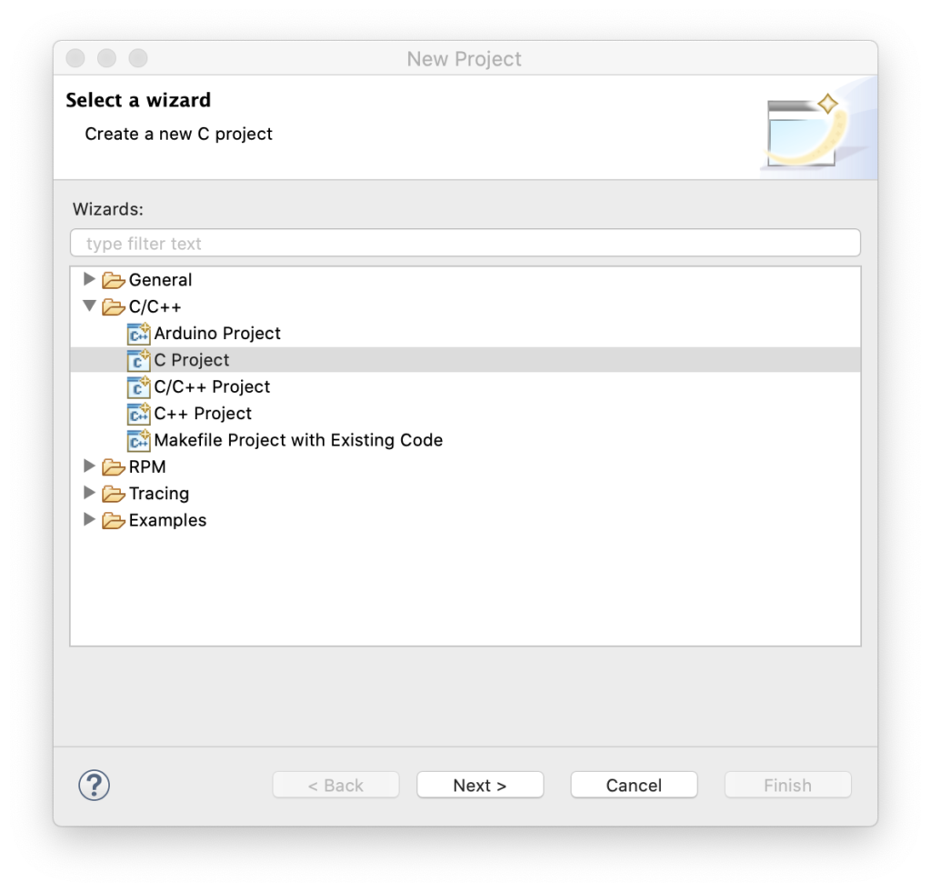
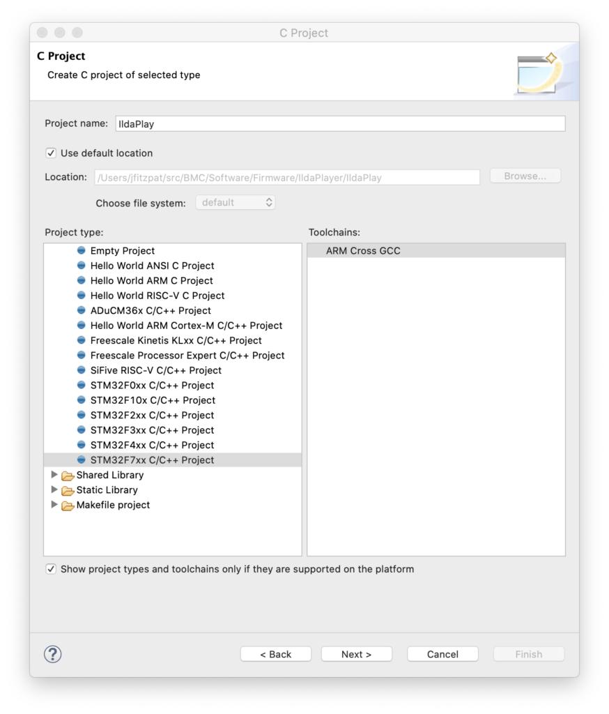
Back when we selected the ARM platform I gave you this link for development tools. This combination makes getting started with firmware pretty easy. In Eclipse, select File / New / Project from the menu and this dialog will appear:
Pick “C Project” then hit next:
Pick a project name and select the template for STM32F7xx (our MCU family) and hit next again:
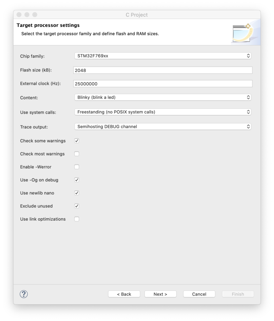
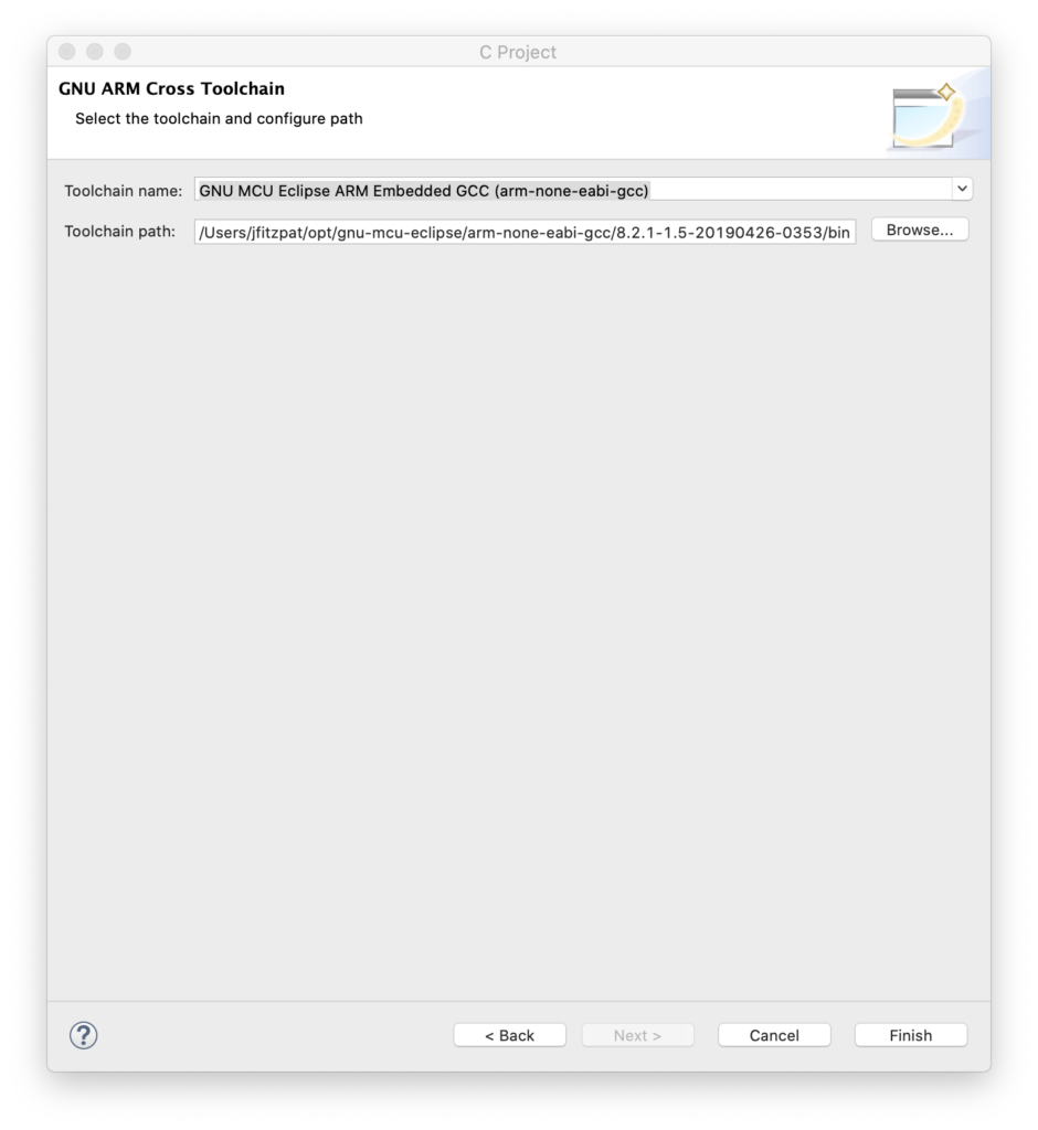
This dialog is critical. We need to enter the correct Chip Family (STM32F769xx), the proper flash memory size (2 meg), and, super importantly, the frequency of the external clock on our board (25 MHz). This wizard automatically creates the initialization code to get all the MCU clocking setup correctly. Having done this from scratch with this ARM family a few times myself, let me assure you this is a real time saver. Anyway, you can just hit next for all the subsequent screens until you get to the last one:
Make sure that this is pointing to your copy of the GCC ARM compiler. At this point you should have a project you can build (Project / Build All). But you’ll also want to run it on the board. To do this you will need to install OpenOCD. That was covered as one of the steps in the link above, but as optional.
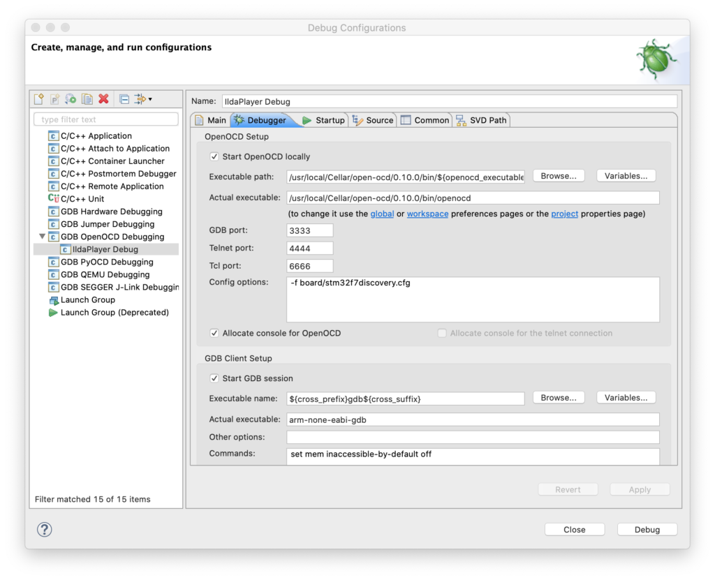
Once OpenOCD is installed you can go to Eclipse, select Run / Debug Configurations from the menu, right click on “GDB OpenOCD Debugging”, and create a new debug configuration.
The key is then the second tab (Debugger). You need to point to the OCD executable with “Executable path” and fill in “Config options” like this:
At this point you should be able to press the “Debug” button and the code will be compiled and loaded onto your card via the USB ST-Link connection. You can single step through the code, or let it run. It will send debug messages, but the LED won’t blink (we have to correct some place holder code for that).
Instead of walking you step by step through correcting a port/pin assignment, let’s just jump ahead a bit. The generated project contains a file called Timer.c and another called BlinkLed.c. I went ahead and replaced Timer.c with a new file called SysTick.c. This is our first ‘module’.
The next module is called TimerCallback.c. This is a simple timer/callback mechanism. Other modules can register a function to be called every x milliseconds. This is our placeholder for an operating system. We might switch to something more sophisticated later, but for now, this will do.
BlinkLed.c, along with a bunch of code in the original main.c are in a third module called… Led.c. This simplifies our main function quite a bit:
int
main(int argc, char* argv[])
{
// Send a greeting to the trace device (skipped on Release).
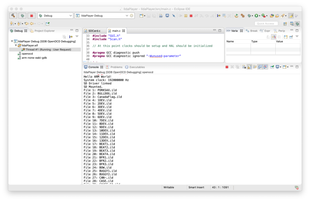
trace_puts("Hello ARM World!");
// At this stage the system clock should have already been configured
// at high speed.
trace_printf("System clock: %u Hz\n", SystemCoreClock);
// Initialize all the modules in their dependent order
sysTick_Init();
timerCallback_Init();
led_Init();
// Infinite loop
while (1)
{
timerCallback_Dispatch();
}
// Infinite loop, never return.
}
The Led.c initializes the LED I/O line when we call led_Init() and toggles the LED on and off every 500 mS when its timer callback function is invoked.