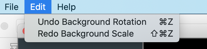
Fixed case where shapes on sketch layer are off screen, then rendered to ILDA points, no truncates instead of wrapping to opposite endge
New Features
Added start and end depth for sketched shapes (Z control)
Added controls for extra points at beginning and end of shapes
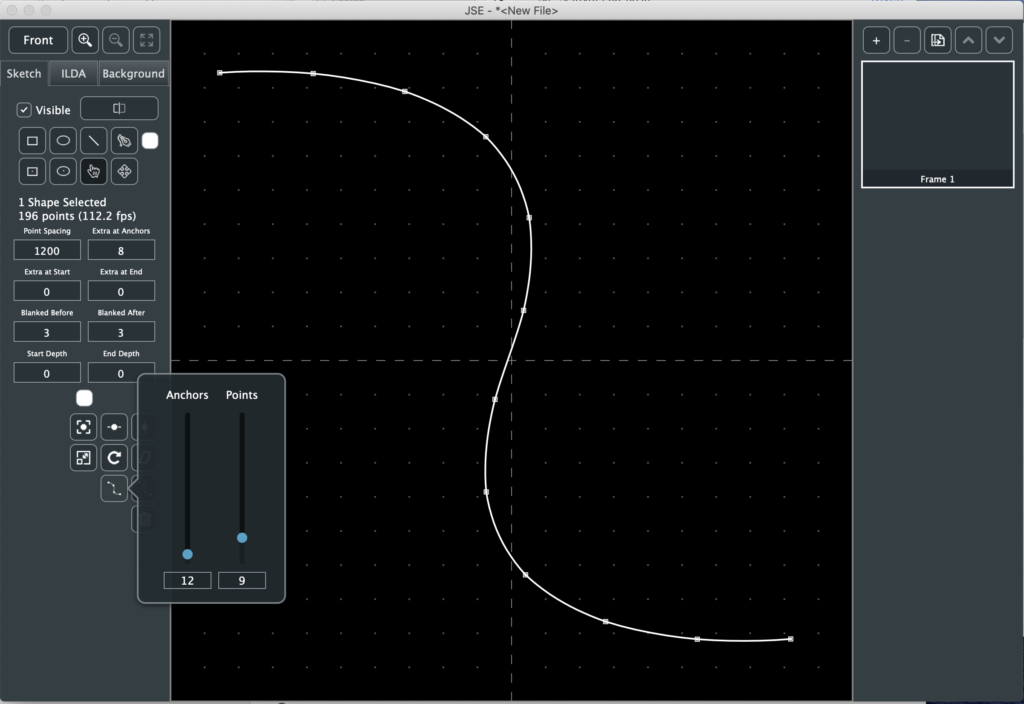
New tool to generate varying number of anchors evenly spaced along shape (user request)
New tool to remove lines between anchors for selected shape(s)
Draw-from-center versions of Ellipse and Rectangle tools (user request)
Menu entries and shortcuts for layer selection and visibility
Menu entries and shortcuts for all tools
Added inc/dec selection for selected anchor on sketch layer (user request)
Notes
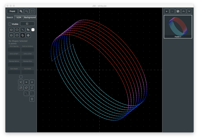
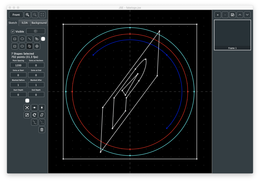
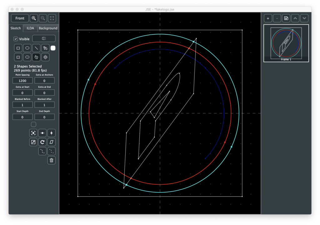
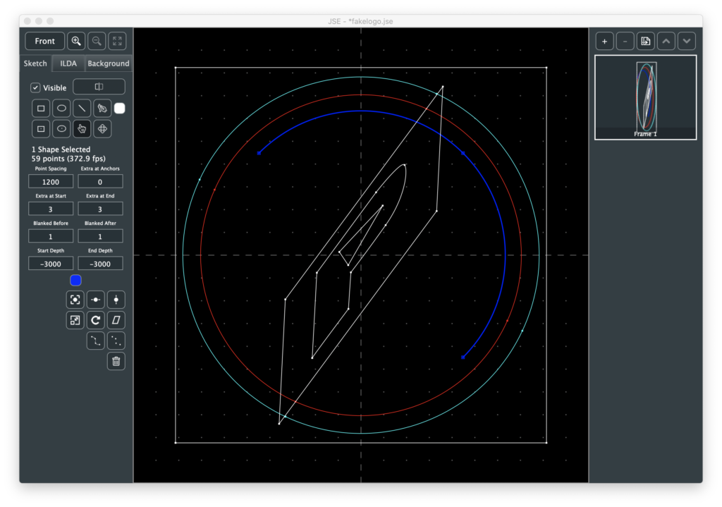
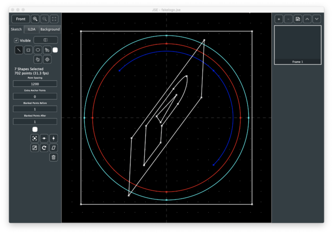
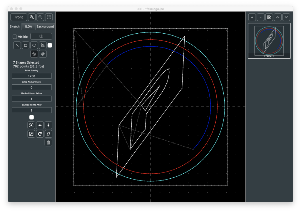
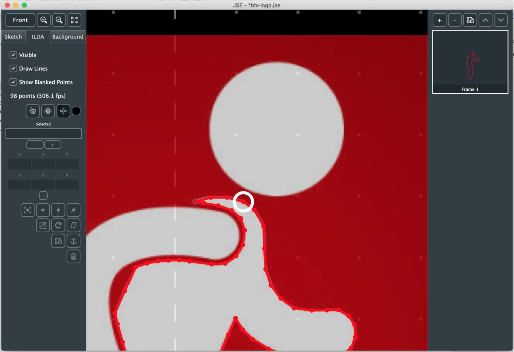
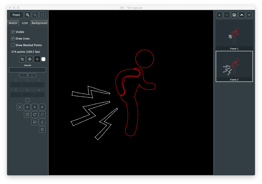
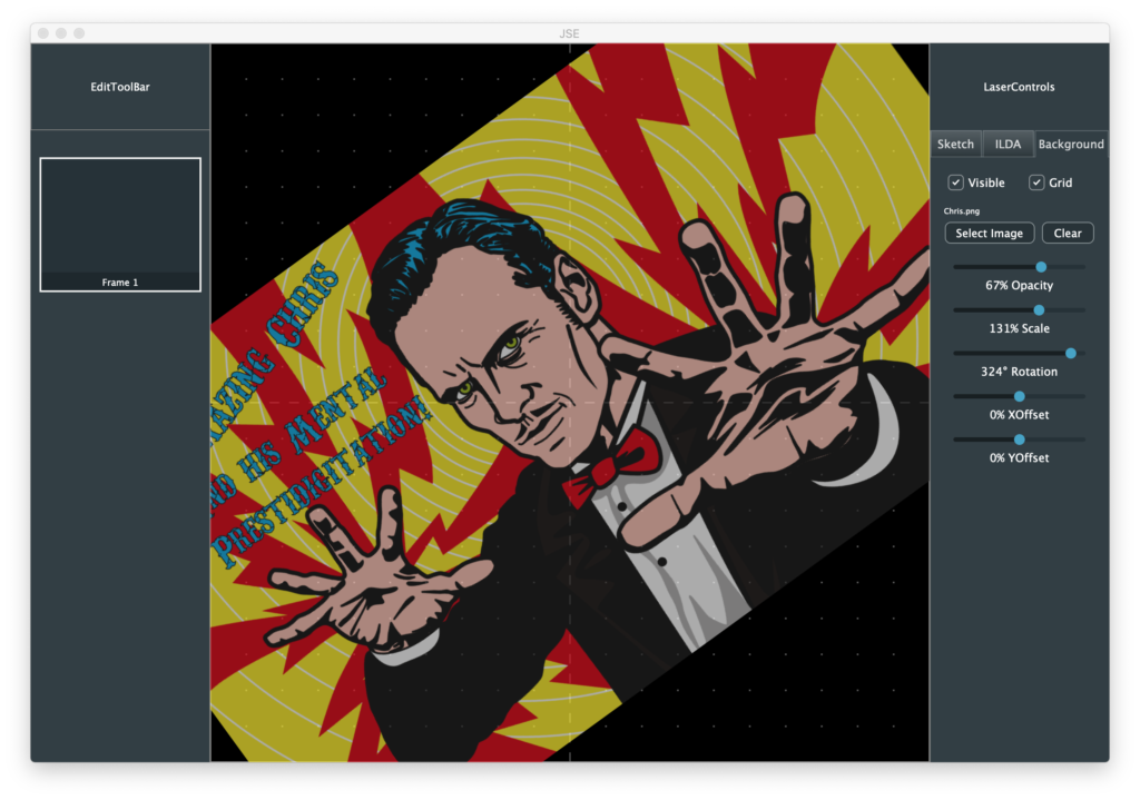
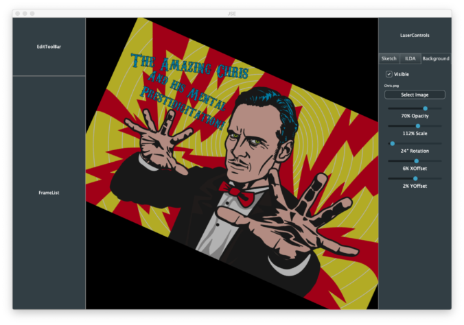
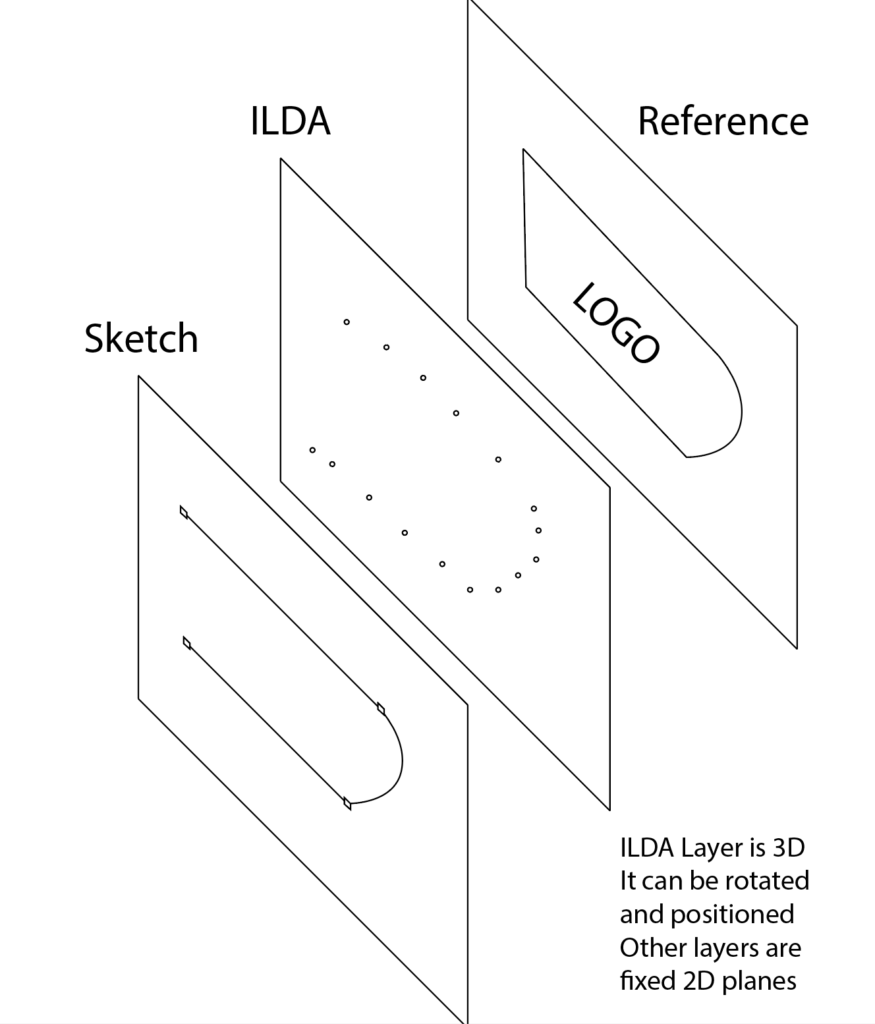
The features this release are all largely unplanned. They grew out of user feedback to the sketch layer and my own attempts to draw simulated logos like this one:
For the most part, the model I envisioned of sketch, render, tweak settings, render… works well. The logo comes up and is recognizable, but the rectangles would look better if the corners were ‘hotter’, so select, change “Extra at Anchors” and render:
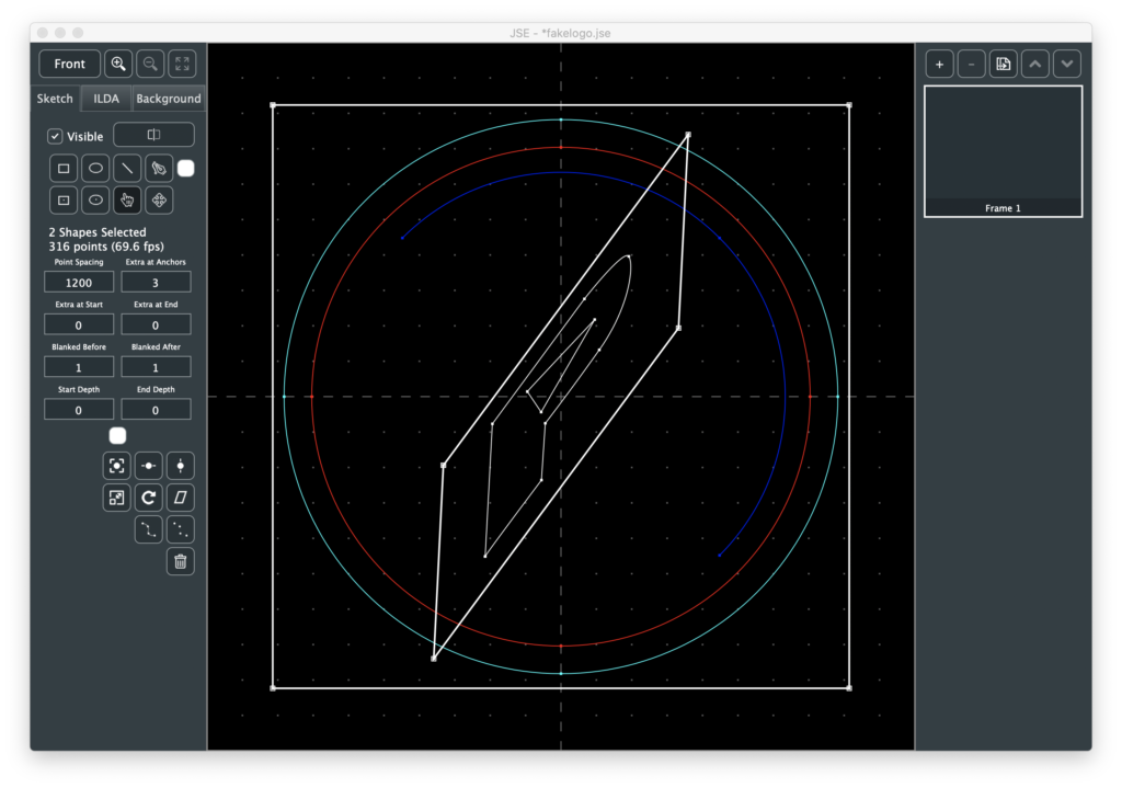
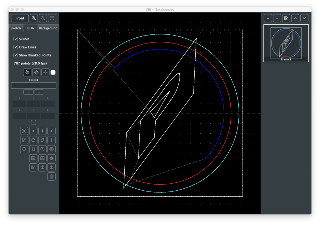
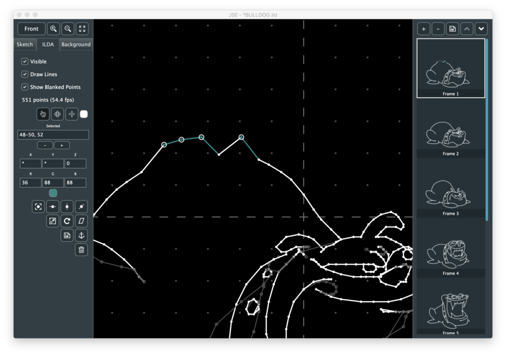
But to make the ends of the blue arc ‘hotter’, I had to go to the ILDA layer and use the point duplicate function. So I added Extra at Start and Extra at End as sketch shape options:
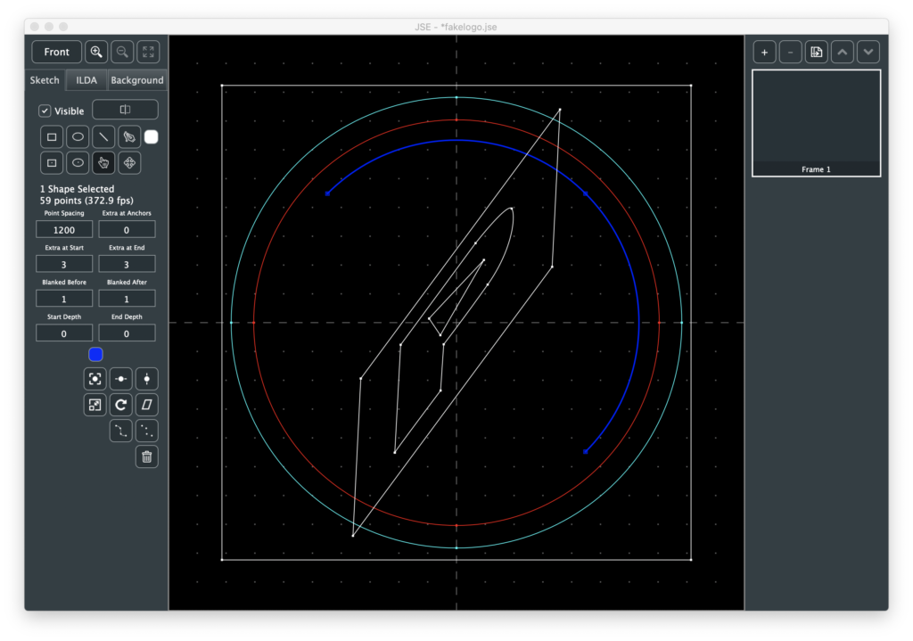
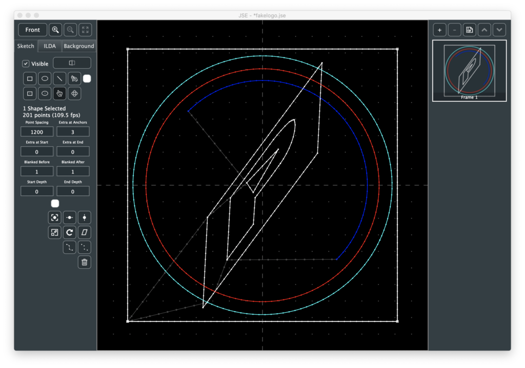
By default, circles start and end at the left edge and I learned that perfect circles are hard to render with the projector I have here. You usually end up with either a small gap or a ‘hot’ overlap. So I rotated the two circles so that the blemish was behind a line on the inner rectangle:
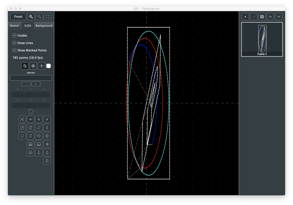
But that made some long blanked lines to and from the start and end of the outer rectangle:
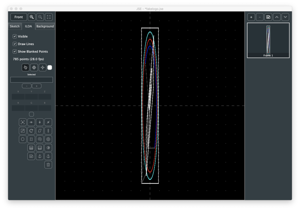
So I scaled that rectangle -100% on the Y axis and rendered again:
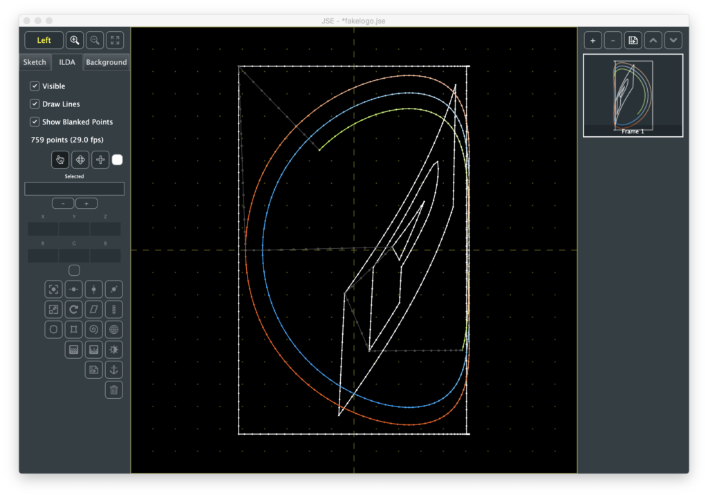
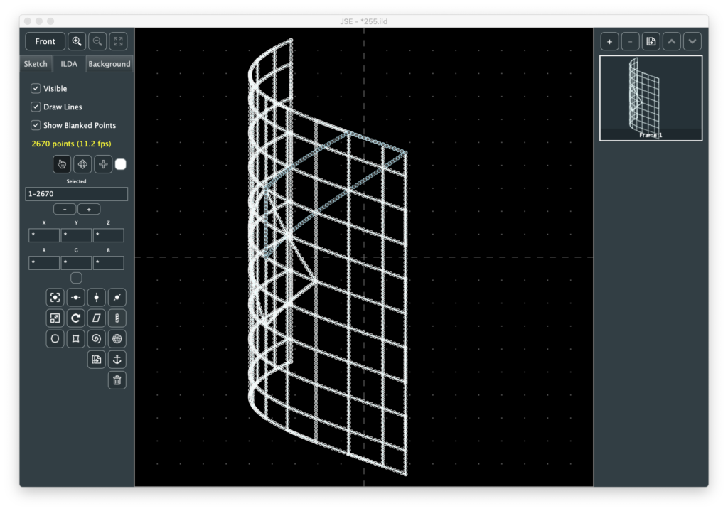
At this point it was looking pretty good, but boring when I rotated it on the scanners because it is completely flat:
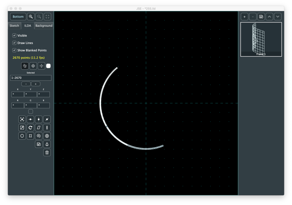
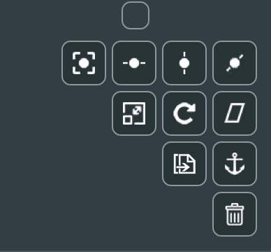
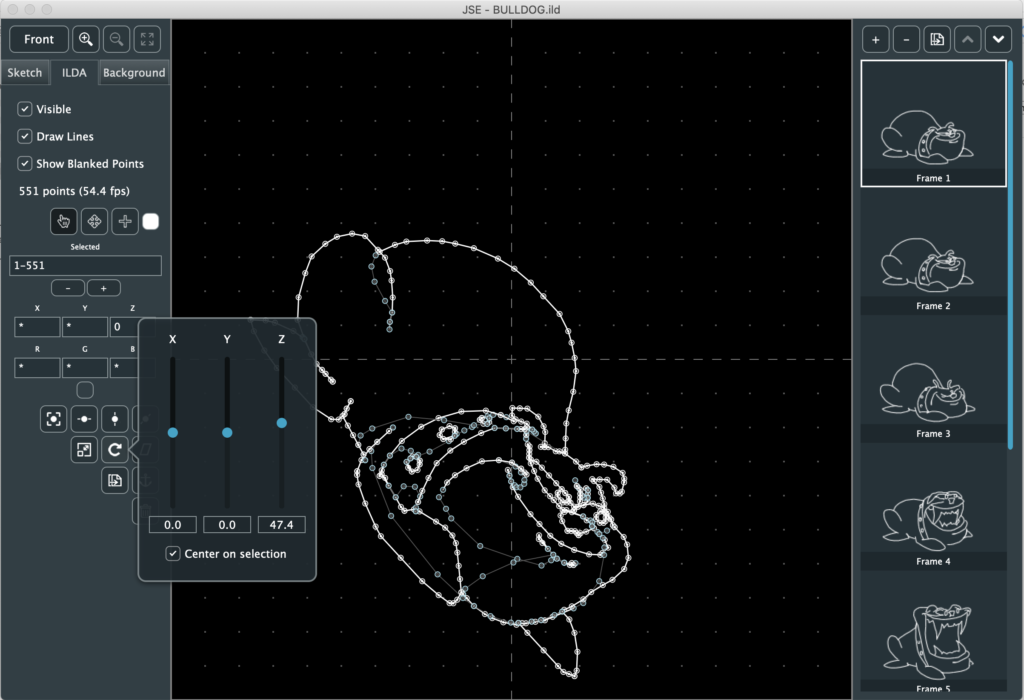
I gave it some Z depth using the ILDA layer, which wasn’t too hard, but a bit tedious, so I added start and end depth control for shapes on the sketch layer:
This wasn’t what I had originally envisioned for 3D drawing, but it is a really quick and easy way to give things a little depth, which makes the log look a lot nicer rotating on the scanners:
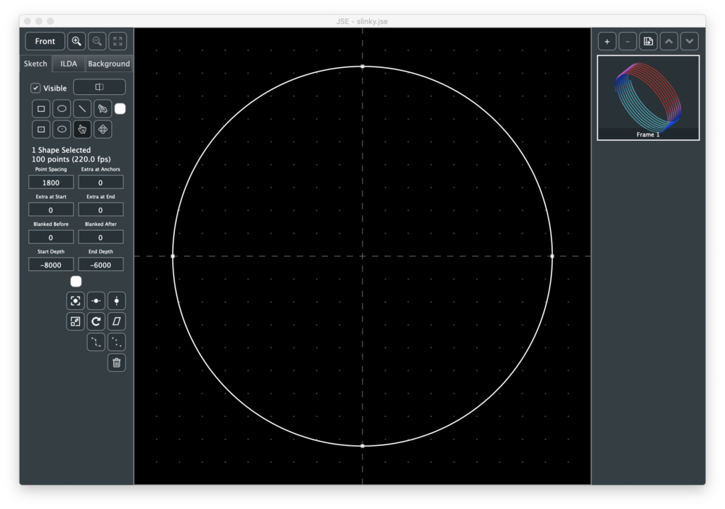
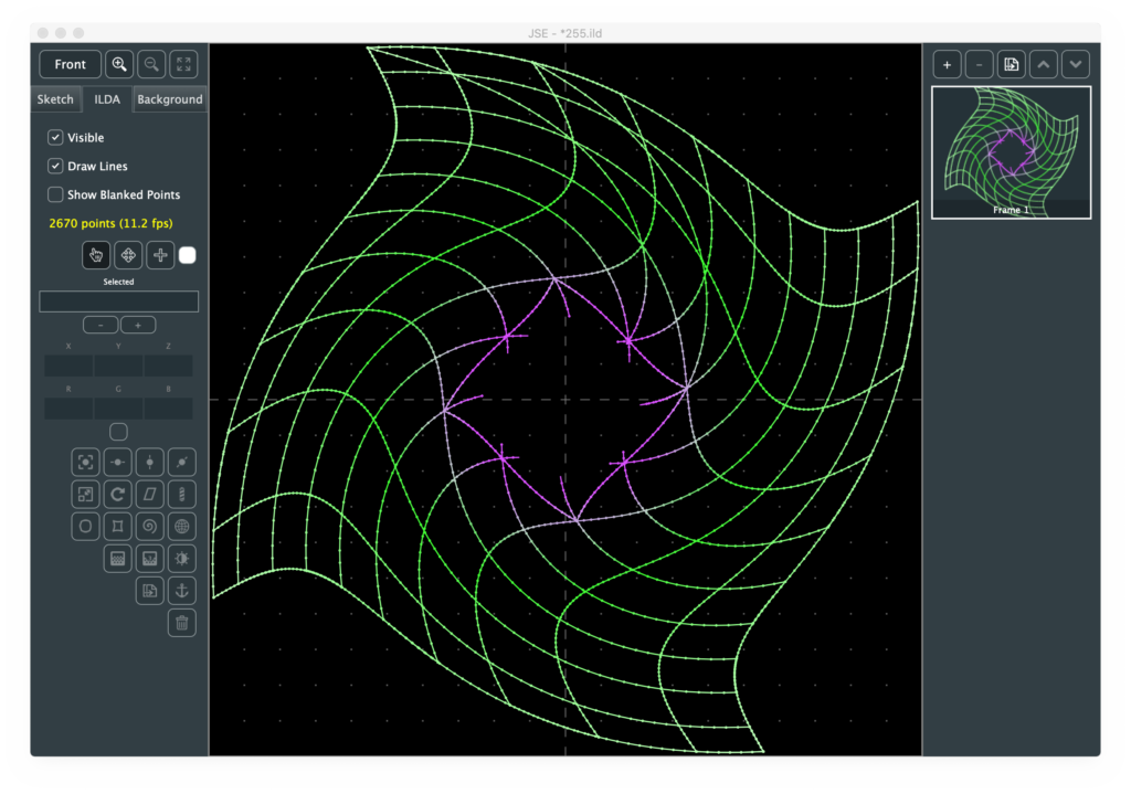
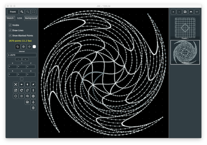
The reason I added start and end is so that users could easily do things like the 3D slinky at the top of this point. I just copied and pasted a circle, changing the start and end with each paste:
I also zeroed out the blanking before and after for most the circles and rendered, giving a nice smooth spiral, which I rotated and colored with ILDA effects.
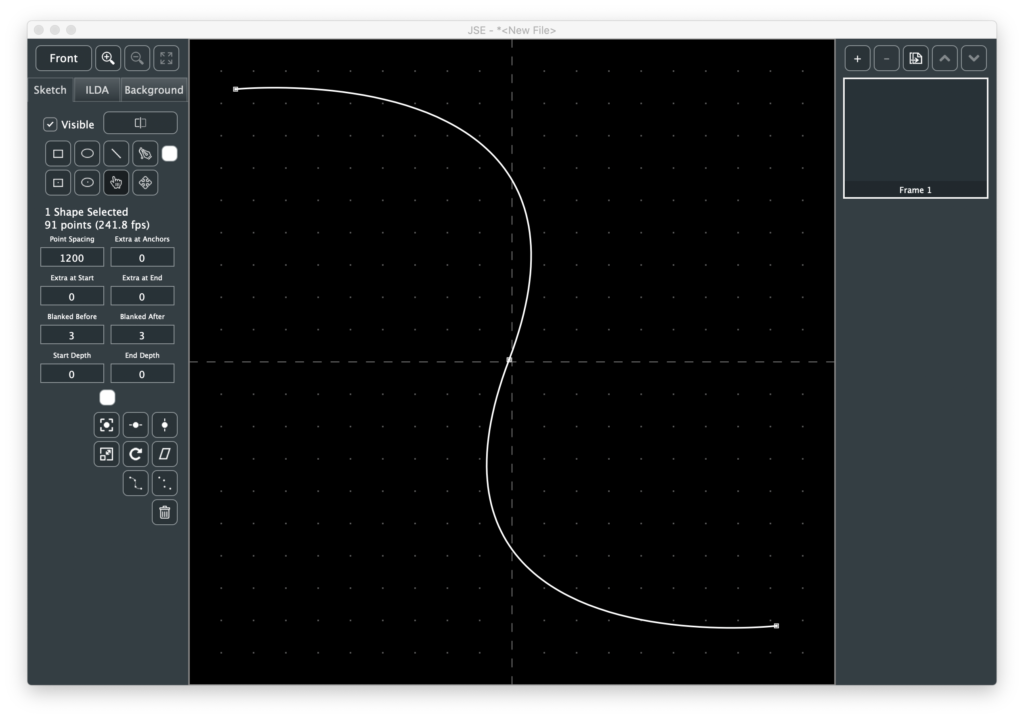
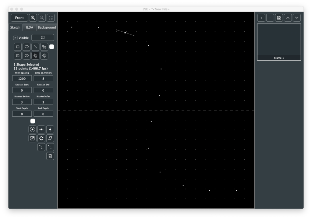
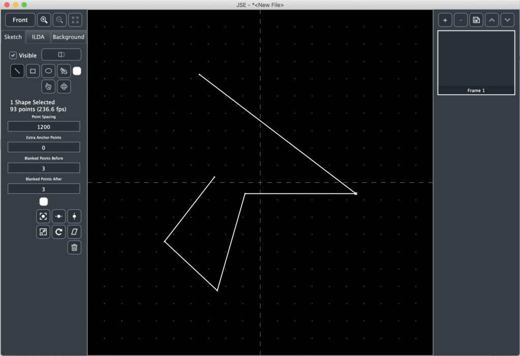
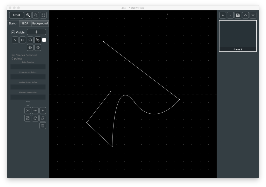
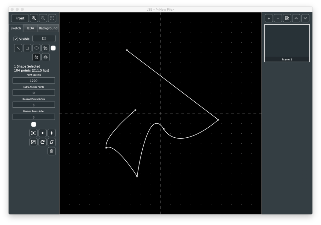
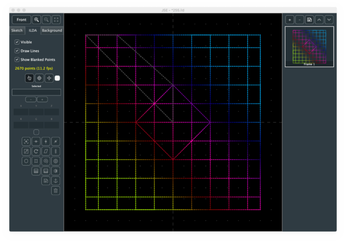
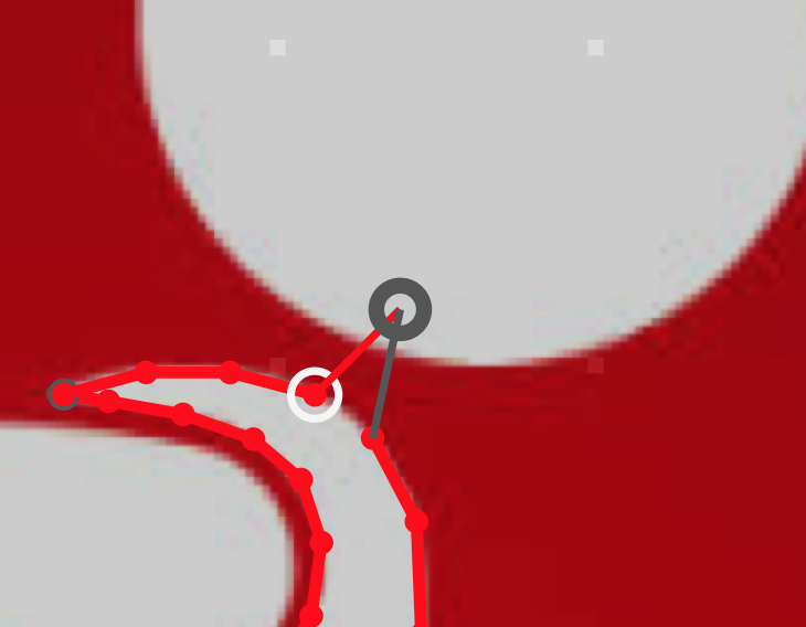
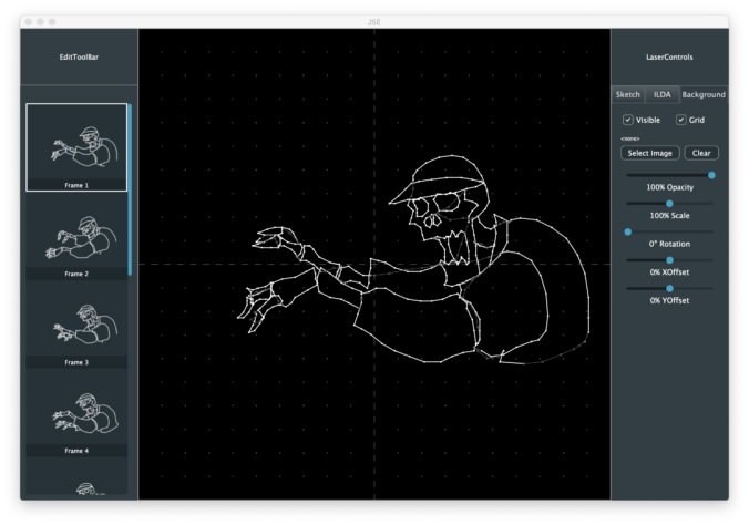
Some other changes were user driven. One request I had was to make it easier to make certain types of images for aerial scanning. You can sketch a shape with the pen:
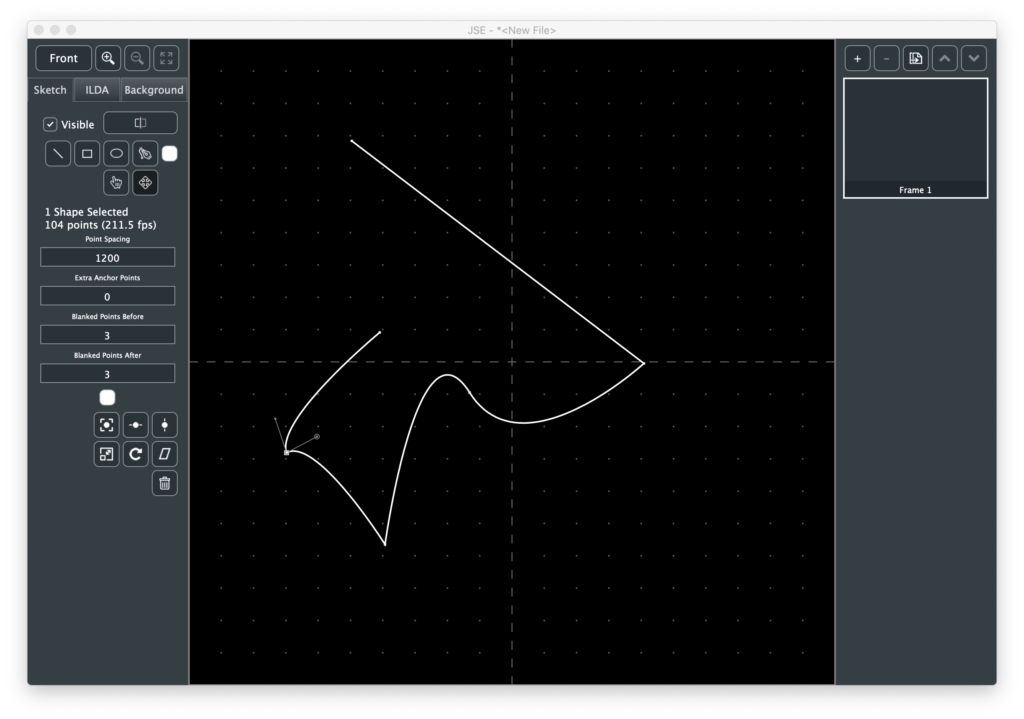
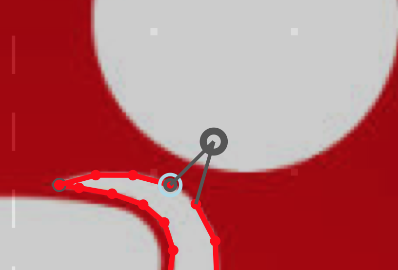
Then have the app insert uniformly however many anchors you want along the drawn shape, replacing any original anchors. You can adjust the “Extra Per Anchor” in the same transform:
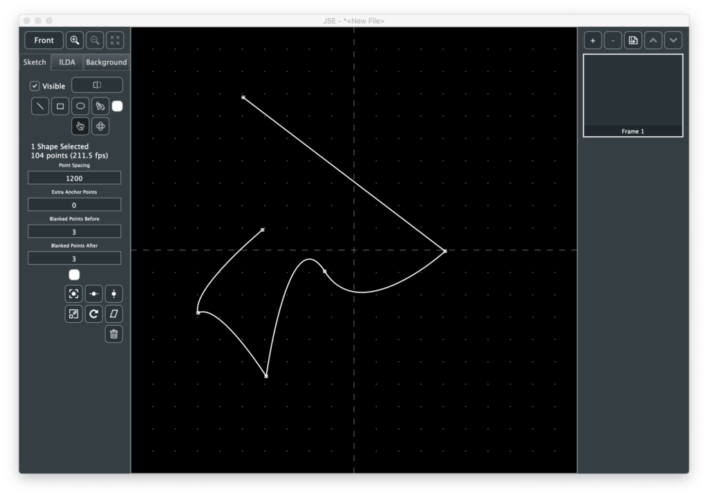
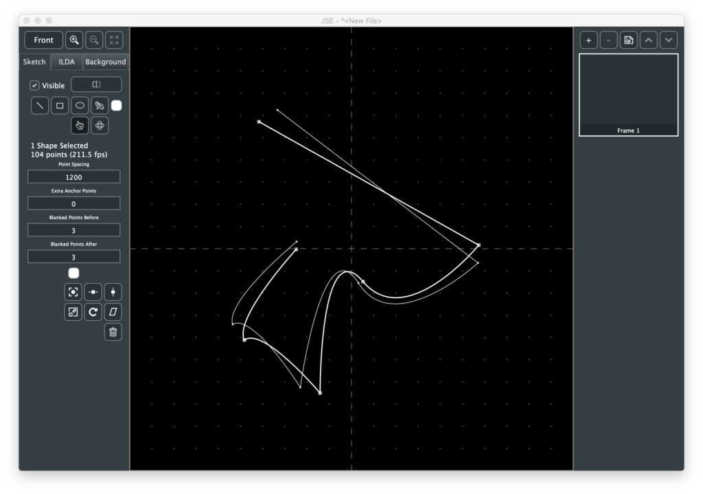
So you have a shape with hot spots in it. If you don’t want the connecting lines, use the tool next to it. That will convert the one shape into a series of single point shapes.
The new shapes keep the info from any original curves just in case you want to select them and use the pen tool to partially redraw the original shape, etc.
There are some other user suggested goodies, like draw from center versions of the ellipse and rectangle tools, but they are all pretty self explanatory.
Fixed bug with frame delete not updating main editor area
Fixed bug with frame rate warning indicators
Fixed crash bug opening some ILDA files
New Features
Sketch layer
Sketch-to-ILDA point renderer with minimum path finder
New shortcut keys and menus for tool selection and other common operations.
Notes
Well, it took an extra week, but this is the largest feature jump since the first public pre-alpha. The big news is that, although I still have some more planned features for it, the “Sketch” layer is now operational.
Just to refresh everyone’s memory, in most existing commercial laser graphic editors that I have seen, you use tools (line, polygon, etc.) to draw and those tools make ILDA points in real time based on current settings (point spacing, etc.) for the tool being used.
My idea with the sketch layer was to separate the process into two steps:
Creating line vector art with tools
Converting (“rendering”) the created vector art into ILDA points
The thinking was to try to maximize reuse and minimize redrawing. If the outline of a logo has too many or too few ILDA points to display correctly, you select that part of the vector art, change the properties of the shape(s), and render again instead of changing tool settings and retracing.
Similarly, you can copy and paste sketched shapes to reuse them, either in the same frame or another. Resize, rotate, adjust corners, and etc., all before committing to ILDA points at the desired spacing. But enough open mic night philosophy, let’s jump right in.
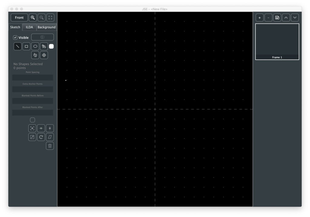
When you open the app the sketch layer, not the ILDA layer, is now the default selected layer:
Like the ILDA and Background layers, there is a checkbox to make the layer visible/invisible. Next to that is the Render button, which we will come back to once we have something drawn. Immediately below the Render button are 4 tool buttons and a color selector to create shapes in different colors.
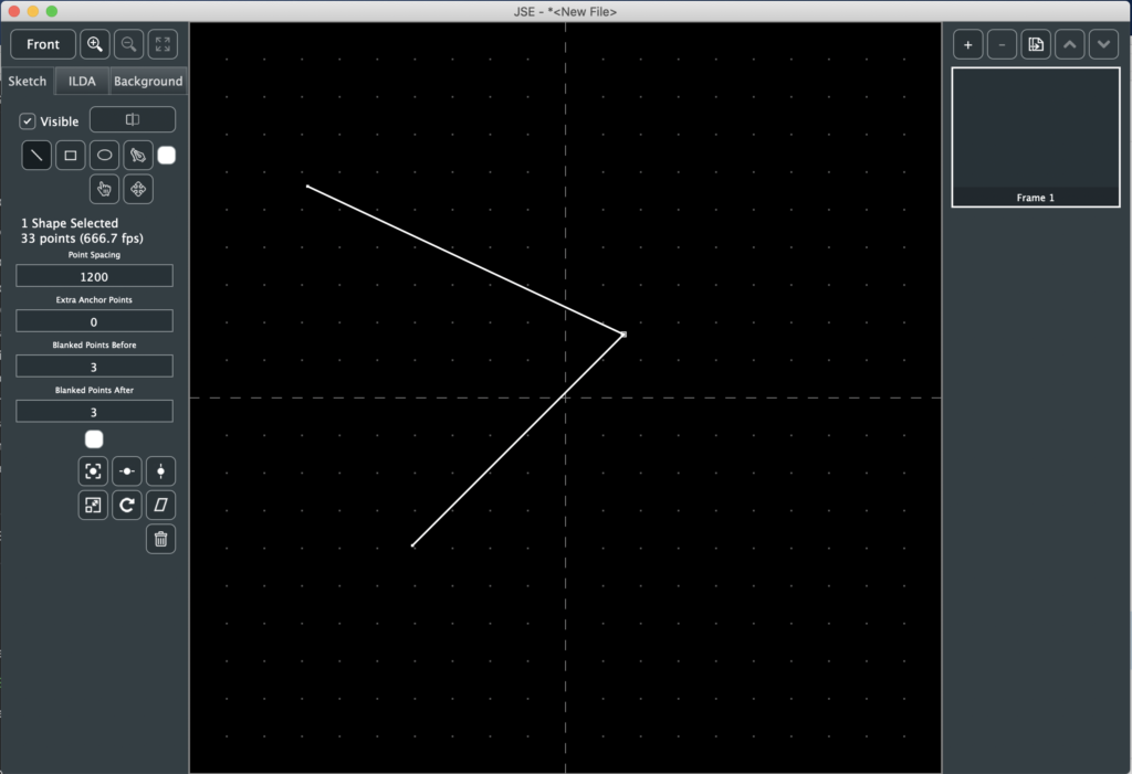
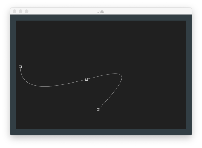
We’ll start with the line tool, which is selected by default. Just point to a spot in the main edit area and click. This will create a new shape with one “anchor”. Move the mouse and click again. There will now be a line between two anchors. You can just keep clicking to extend the straight line shape. The behavior is very similar to the point tool on the ILDA layer covered in the JSE 0.1.1 release notes.
A rubber band shows the potential line from the last placed anchor. If you hold the <shift> key the angle of the next segment will be constrained to the nearest 45 degrees (0, 45, 90, etc.) If you hold the <ctrl> key the end of the rubber band will ‘snap’ to an existing anchor if one is close by.
When you are done with a line, hit the <esc> key and you are ready to start another line based shape somewhere else.
The next two tools are “Rectangle” and “Ellipse”. The use of both is very similar. Click and drag (hold the mouse button down) in the main edit area. A thin grey outline will show the shape. When you release the left mouse button the shape will be created.
If you hold <shift> with either tool, width and height will be locked together so you can draw squares and circles.
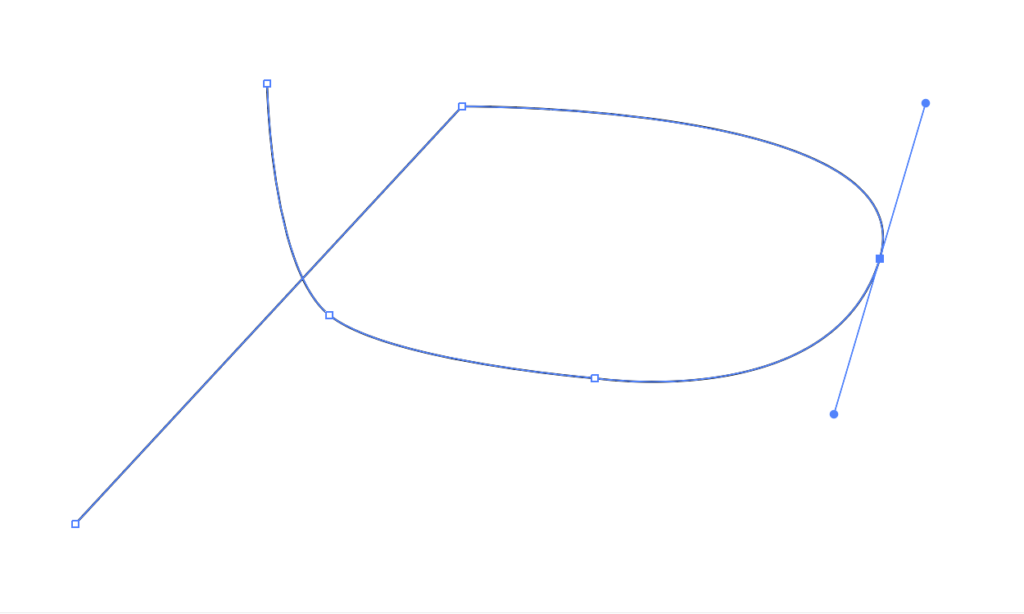
The Pen Tool is a simplified implementation of the pen tool in Adobe Illustrator. If you just click, it will work like the line tool. But if you click and drag when placing an anchor, you can make the connection to the previous anchor curved:
Like Illustrator, the assumption is for the line to leave a curved anchor in a complimentary curve. And, also like illustrator, you can straighten the anchor ‘exit’ (leave the anchor using a straight line) by pointing at the anchor right after you create it and clicking again (or by selecting “Straighten Anchor Exit” from the Edit Menu).
Like the line tool, you can <shift> and <ctrl> to either constrain the pen tool to 45 degree angles or snap to an existing anchor.
Below the shape creation tools are two more tools. The first, a hand, is the Select Tool. With it you can select one or more complete shapes, a specific anchor on the the shape, or the curve controls for a curved anchor:
Like the ILDA layer, whatever is selected can be moved with the arrow keys (hold <shift> for smaller steps) or deleted with the <backspace> key.
You can also move things with the mouse using the Move Tool next to the Select Tool. Like the select tool, what you are about to select is highlighted, but you can then click and drag to select and move an object with one operation.
If you click and drag in blank space (nothing highlighted under the mouse cursor), any already selected items will be moved. This can be handy for any curve control handles that may be off screen.
First select the anchor, by clicking on it with either the Select or Move Tool. Then select the desired curve control (entry or exit) for that anchor using either the Edit Menu or the shortcut keys shown in the menu (<;> for entry, <‘> for exit). Once the control is selected you can then move it by clicking and dragging in blank space with the move tool.
If you are moving an anchor, holding the <ctrl> key will let you ‘snap’ it to an another anchor’s location.
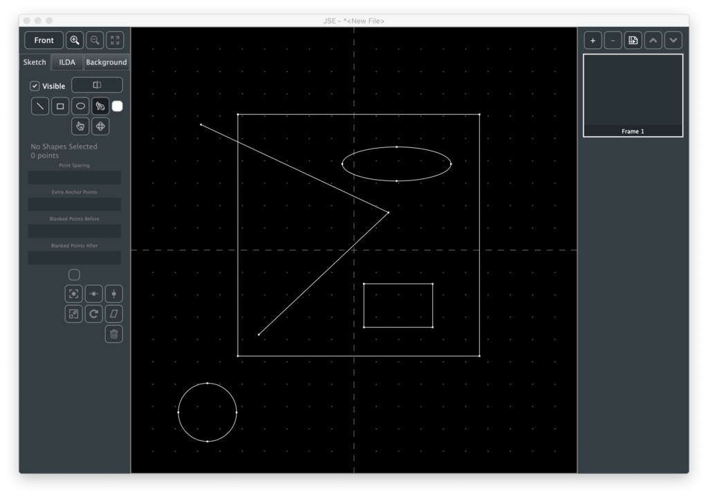
If you play with the select and move tools you will quickly realize that the shape creation tools don’t really create different things. They all create anchors which are connected to each other with “Cubic Bézier Curves“.
This lets you mix and match tools. For example, start by drawing a simple shape with the line tool:
To add anchors to this shape later we select an existing anchor with the Select Tool. The Line Tool will then show a rubber band to the mouse from the selected anchor and then back to the next anchor (if any):
We could click to add additional anchors, but let’s say we want the new segment curved. Hitting <p> will switch from the Line Tool to the Pen Tool. We can then insert curved anchors into our previously straight lined shape:
Of course, we could have selected the Pen Tool using the button or the Edit Menu, but the shortcut key let’s you do it without moving the mouse, which can be handy if you are tracing a loaded background image, etc. See the Edit Menu for a list of all the available tool shortcuts.
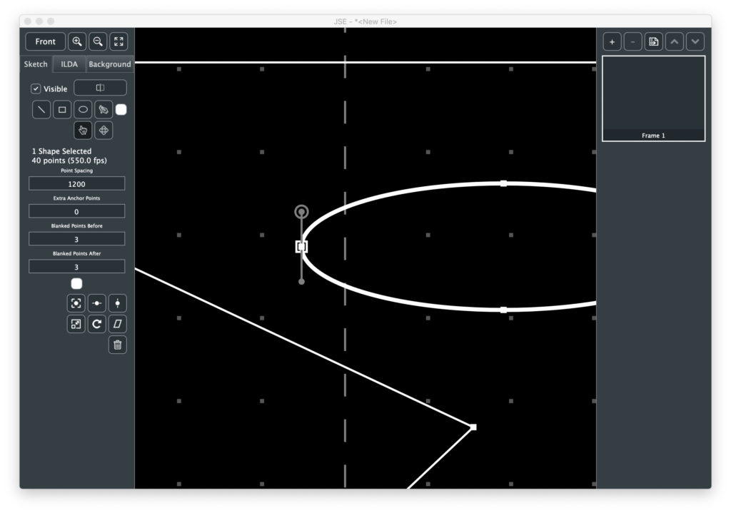
You can go back and forth between curved and straight for existing anchors as well. Just select the anchor and pick “Straighten Anchor” or “Curve Anchor” from the Edit Menu. Once an anchor is curved, you can adjust the control handles to get the shape you want:
When one or more shapes are selected, some info is populated and displayed below the tool selection buttons. The four edit boxes control how the shape(s) will be rendered. Point Spacing controls the average gap between generated points.
Don’t panic that the default value seems so large (1200). JSE is a 16 bit editor. It exposes all the resolution available in an ILDA file. Many commercial editors expose lower resolution. You can tell this by checking the available XY coordinates. If a system goes +/- 8,000 instead of +/- 32,000, it is creating 14 bit images and a point spacing of 300 would be equivalent.
Extra Anchor Points is just as its name implies. It will add extra points at each anchor location. This is for things like making the corners of a rectangle brighter and sharper.
The last two fields control how many blanked points are placed at the first and last anchor points before and after a shape is scanned.
Below the edit boxes is another color selector. This let’s you change the color of shapes after they are drawn.
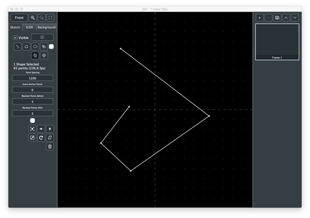
Next are some simple transforms that can be applied to selected shapes. To get a feel for those let’s first select our new curvy steam punk hatchet head. Note, we want to select the whole shape, not just one anchor:
The first three transform buttons are just for centering, on the X axis, the Y axis, or both:
Before using the other transforms, let’s copy and paste our selected shape using Copy and Paste from the Edit Menu, or the <cmd/ctrl> + C and <cmd/ctrl> + V shortcuts.
At first, it might seem that nothing has happened, because the paste put the copy at exactly the sample place, but it also selected the pasted shape(s). So we can move the copy with the arrow keys or transform with, say, the Rotate button:
In addition to Rotate you can Scale (bigger, smaller, or invert) and Shear/Skew selected shapes. Like the ILDA layer, transforms can either be based on the center of the edit field or the center of the selected shape(s).
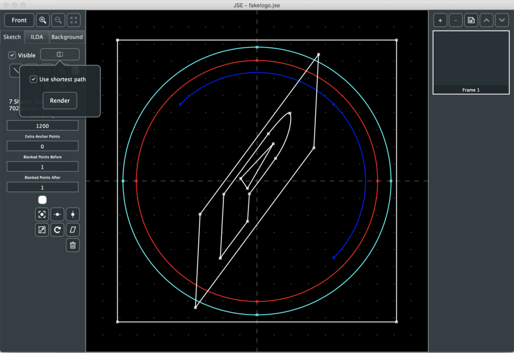
Now that we have some shapes, let’s use the Render button. Because it will be getting more options, the button invokes a popup:
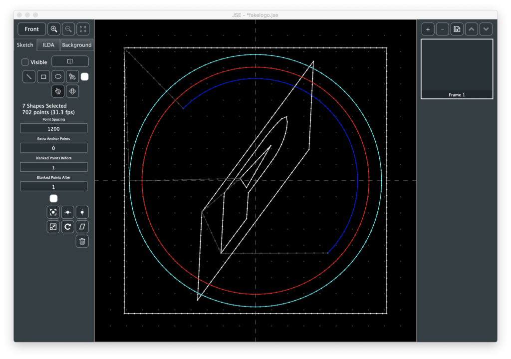
In this version, the only available option is “Use shortest path”, which is on by default. To better understand this option, let’s click on the Render button, then hide the Sketch layer and look at the ILDA result:
To be an ILDA scan, we need to do more than just convert each shape into points. We need to connect all the shapes together with invisible lines and form a loop. This is a variant of what is called the “Traveling Salesman Problem” (TSP). Basically, how to visit everywhere you need to go while traveling the shortest total distance. It is one of the classic, surprisingly difficult nerdvanna-type computer science problems, with graduate students striving to make even minuscule improvements in computation time.
In our simple case, one of the classic approximations, “Nearest Neighbor”. combined with “Arbitrary Start Node” works well. Basically, after each shape ends, the closest start or end of another shape is found. This repeats until there are no more shapes. The total connecting distance, including the return to the first shape, is tabulated. The program tries this starting at the beginning and end of each shape, and then uses the combination with the lowest connecting length.
Most the time, this works quite well. But there are cases where you want points in a very specific order (ex. a signature you want to trace out). In those cases you can turn off the Shortest Path option and the shapes will be scanned in the order and direction you created them:
This will almost always result in more total points in the ILDA image, but gives you complete control over order.
Regardless, if you don’t like the point spacing, etc. of a given shape you can adjust that shape’s parameters and render again. Once you are happy with the Render output, you can hide the sketch layer and use the ILDA layer to tweak or add specific points, apply color effects, 3D Transforms, etc.
Still lots to come, but hopefully it is starting to feel more like a real content creation tool.
Fixed a rounding error with center-of-selection calculation
New Features
Added 2 and 3 color gradient tools
Added Hue, Saturation, and Level adjust tool
Point selection markers now hide during transforms/adjustments
Notes
For anyone following the commit count on GitHub, I did not have much time to work on JSE since the last release. Work, sports playoffs, zombie apocalypse… take your pick. In the one short session I did have, I squeezed in some basic color tools.
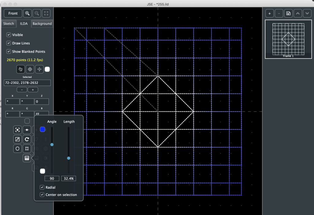
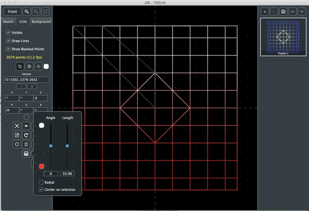
Both gradient tools are pretty simple. You can do a radial gradient:
With a color fade that is circular to the center. In this case, the colors, length of the gradient, and what center to use (center of the ILDA grid or center of the selected points) are the primary controls.
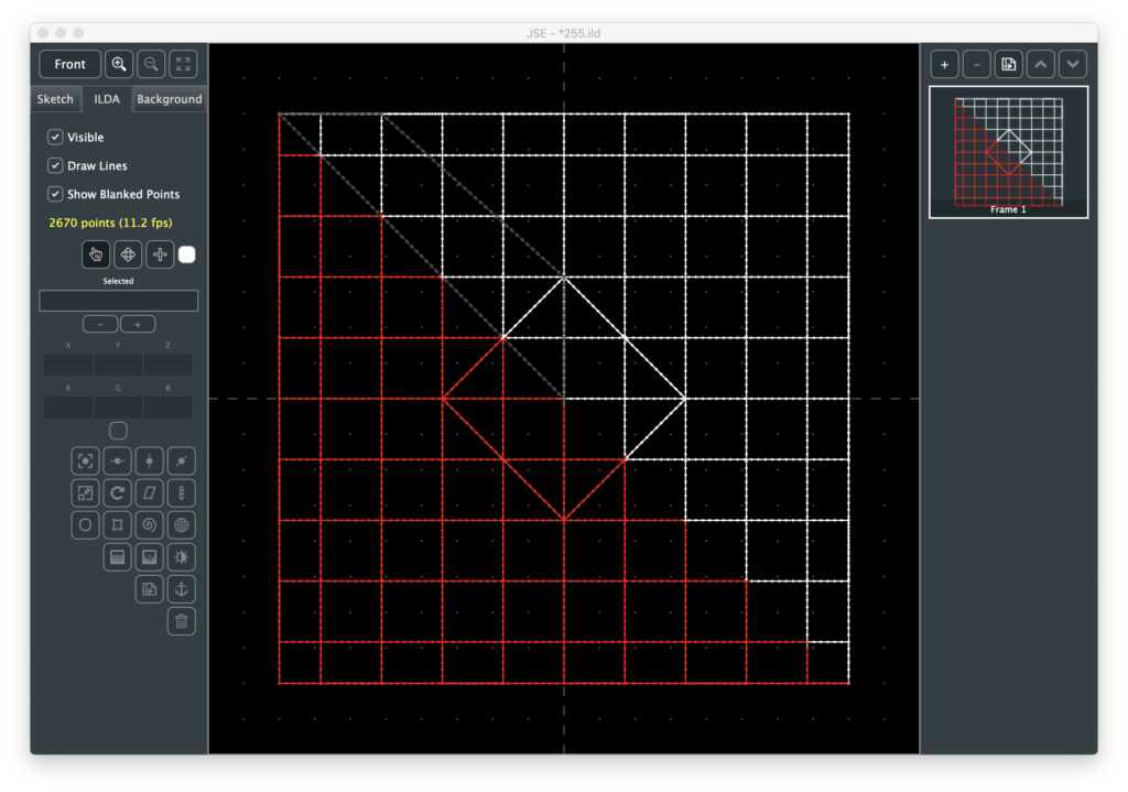
If you choose a linear gradient (not radial), you also have control over the angle the gradient travels across the selection or ILDA grid. You can make the gradient length very short and basically step between colors:
It’s important to note that the gradients are relative to the current view. So you can set them up based on Z position as well as X and Y:
The 3 color gradient tool is identical except that you get to pick a color in the middle of the gradient between the other two:
You can also pick black as a color. If a point is adjusted to black, it is blanked:
We generally refer to the color of an ILDA point in terms of RGB, or Red, Green, and Blue. But there are other ways to identify a color. These are usually called a “Color Space”. For example, video often is expressed in “YUV” color space, printing often uses CYMK color space. One color space that seemed kind of handy to me for lasers is HSL, or hue, saturation, and level.
The best way to get a feel for them is probably to throw a color gradient across an image and just play. Hue in particular is kind of fun.
One thing I noticed in color adjustments is that the selected point markers obscured the adjustment, so I changed the app to not draw them in the middle of a transform operation. That is, they will disappear when one of the popups with controls appears, then come back when the panel is dismissed.
Sorry for the thin list. I’ll try to get more in for the next release!
Fixed a bug where you could not delete and undo the last frame
Fixed a bug where you could operate the menu bar during transform operations and get undo out of sequence
New Features
Five new selected ILDA point transforms
Barber Pole
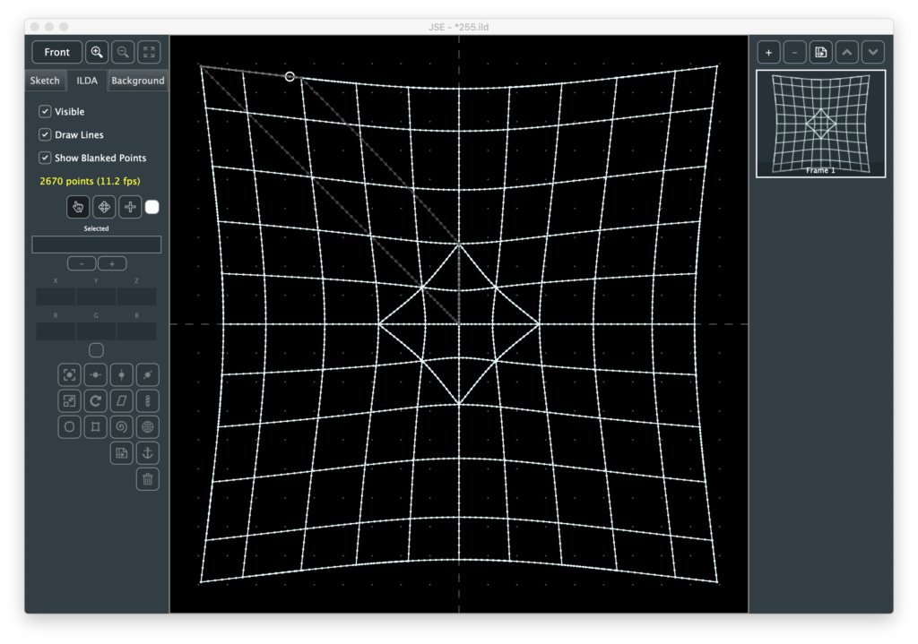
Bulge
Pinch
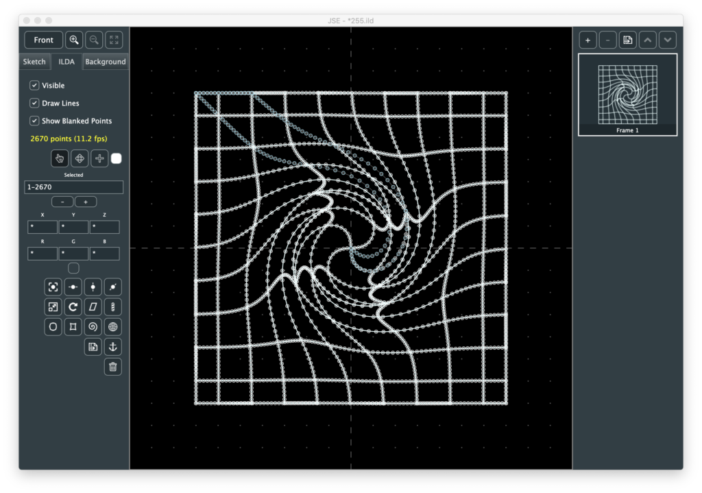
Spiral
Sphere
Right click context menu for Ilda Selection Tool
Notes
Originally I wasn’t going to put in 3D transforms at this point, but later when I do a simply animator/frame generator. But I needed one, then the dust was kicked off my Euclidian math brain cells and a single new transform button on the ILDA properties pane looked lonely, so…
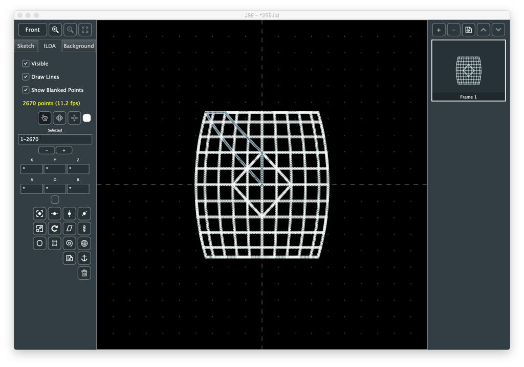
Barber Pole wraps the selected points around a virtual cylinder. You can control the radius of the cylinder. Although they are available as separate transforms, I put one axis of skew/shear and Y rotation on the same popup:
I made the matrix order skew, cyl transform, rotate, so you can get some nice perspective type looks like above, but if you look from the bottom you can still see it is a cyl:
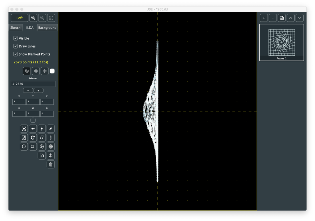
Bulge and Pinch are really the same transform. The coordinates are converted to from cartesian to polar, then exponentially adjusted and converted back.
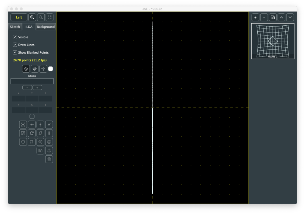
This is just a quick and easy way to get the desired visual effect without contour mapping and doing a projection. If you look at the converted image from the bottom or side you can see it is still flat:
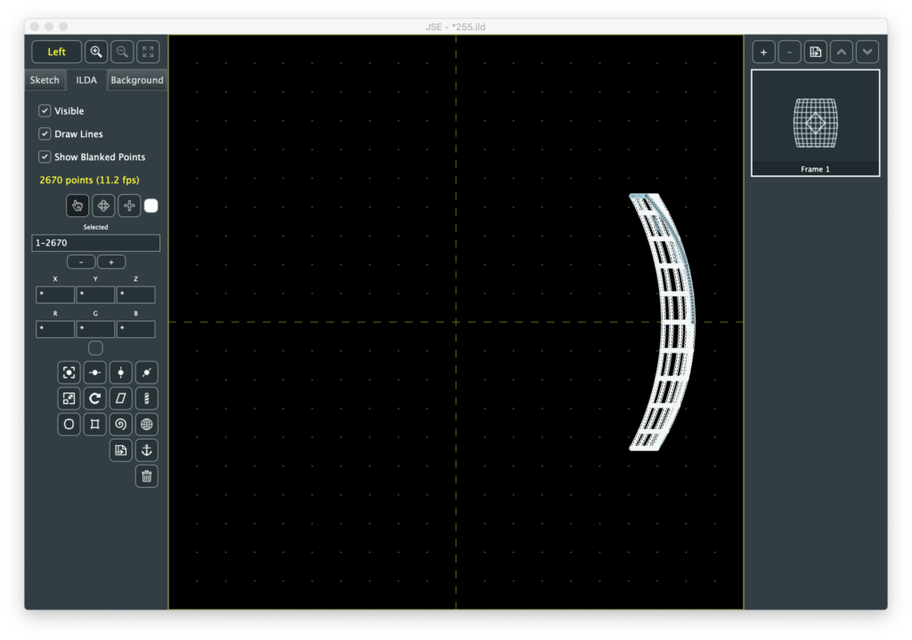
Spiral is basically a drain effect.
You can control the amount and direction of the swirl and the size of the vortex, giving this one a lot of versatility. I do transform the vortex as a Z offset:
But you could force all the Z coordinates back to 0 and the front view would look exactly the same.
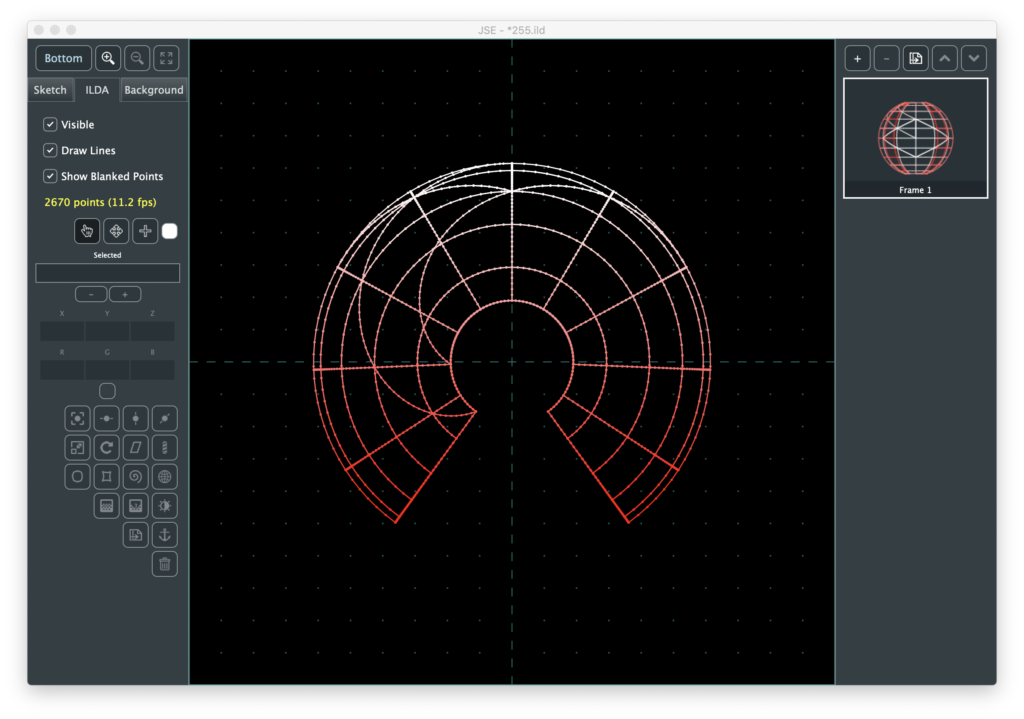
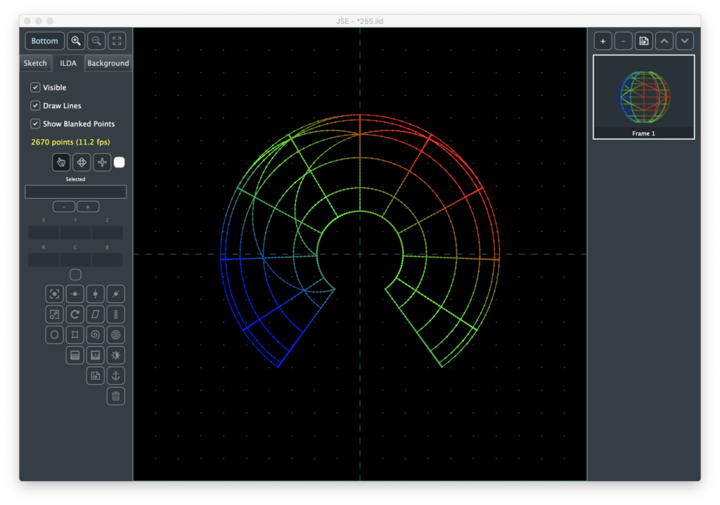
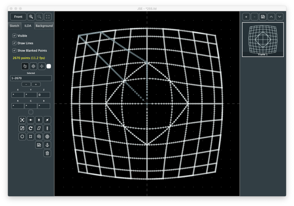
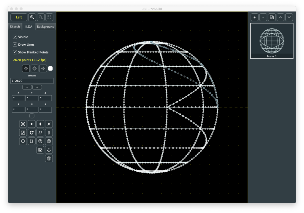
Sphere, as it’s name implies, stretches ILDA coordinate space around a perfect sphere:
By default, the ILDA plane is stretched twice as wide as it is high, so that it fully covers the sphere. But you can control the radius of the sphere and independently adjust X and Y scale so you can control how much or little of the sphere surface is covered (or even covered multiple times):
This is a nice way to create some pieces with some contour to fly around, but it also shows why I went with the exponential polar transform trick for bulge and pinch. Without a good projection transform, these kinds of mappings look very Star Wars like.
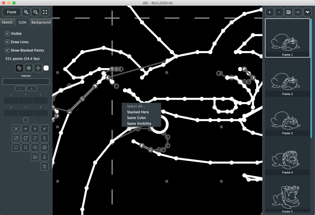
The Select Tool Context Menu came out my own use. Often anchor points are stacked on top of, or almost on top of each other. You can select all those points by dragging a rectangle around them with the select tool, but that isn’t always convenient, so I added a right click menu you can use when a point is highlighted:
It let’s you find all the points (“Stacked Here”) that would have passed the proximity test (instead of just the first one, like when you left click):
You can then move or alter those points as a group. Since I put in a menu, I also added the ability to select points of a matching color or visibility, which can be useful when modifying coloring:
If you right click without highlighting a point you get the option to Select All or Clear the current selection.
Not as much as I had hoped to squeeze in this week, but I didn’t have a ton of time to work on it. More soon though, I promise! I’ll also try to catch up a bit on design and execution backstory.
This week we’ll take a break from my normal drivel about how the different pieces of BMC are being developed and cover a public release, pre-alpha , of my simple ILDA editor.
For those jumping in cold, ILDA is an industry association for laser entertainment. When I refer to ILDA here I am talking about the association’s standard for exchanging laser graphic information. Although the standard dates back to the 1980’s, the projection technology still hasn’t really outgrown it. As I explained early on, it is basically a game of ‘connect-the-dots’, with the laser beam quickly tracing a pattern. It’s a bit like a fast Etch-a-Sketch, but the laser at least can be hidden, or ‘blanked’ for part of the trace.
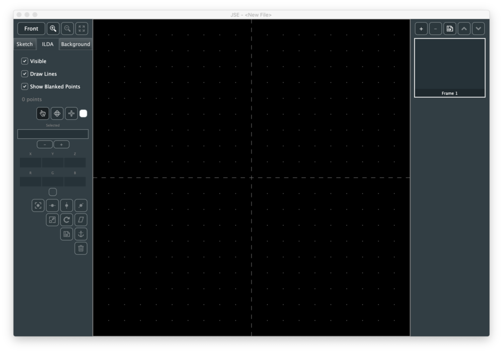
Warning! This is pre-alpha software! That means it is far from full featured and has not been extensively tested. Please use with care. Particularly when it comes to playing any generated ILDA content on scanners. That said, let’s cover what is working. When you start JSE on either Windows or Mac you get a default file with 1 frame, and no points:
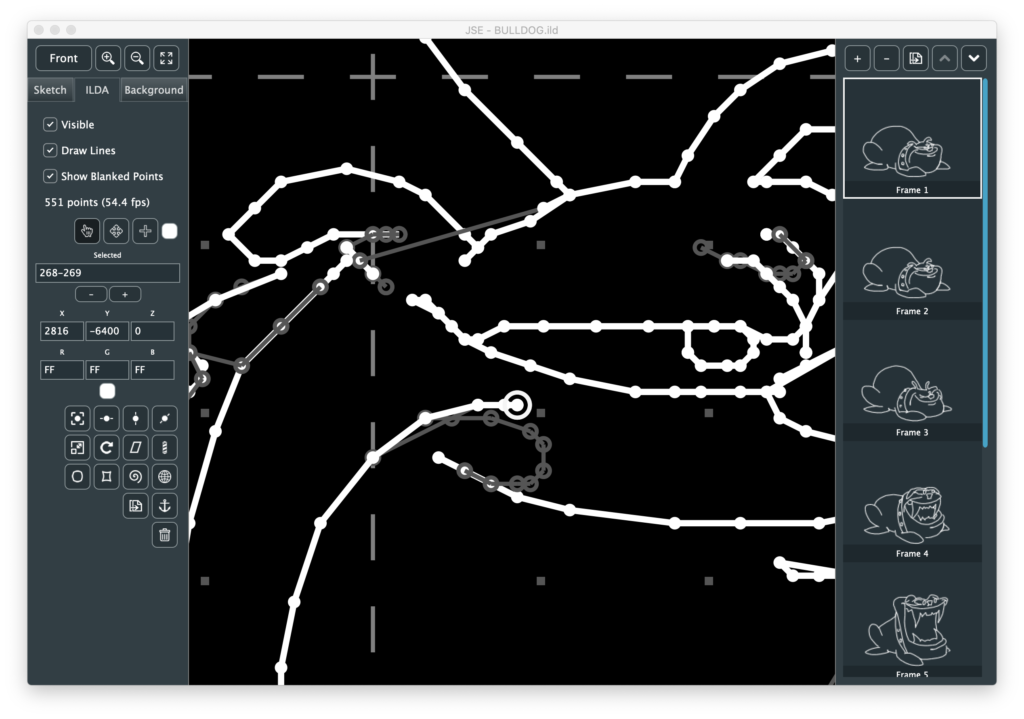
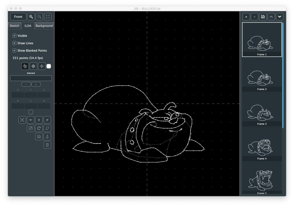
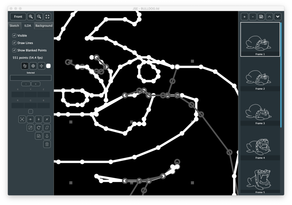
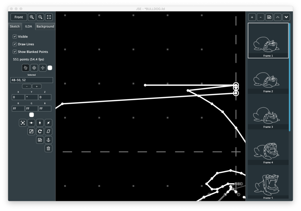
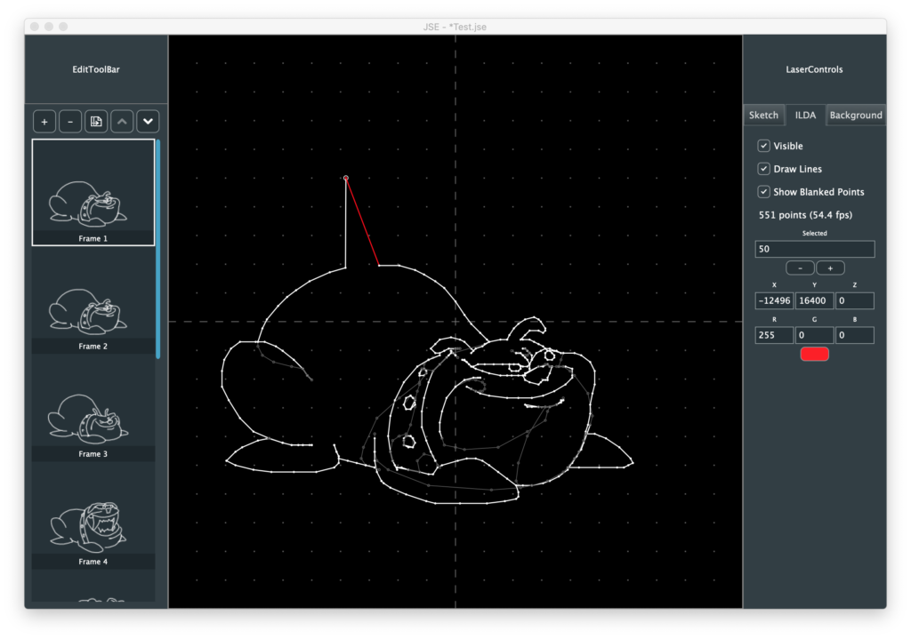
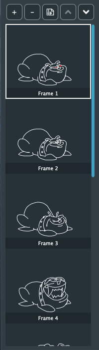
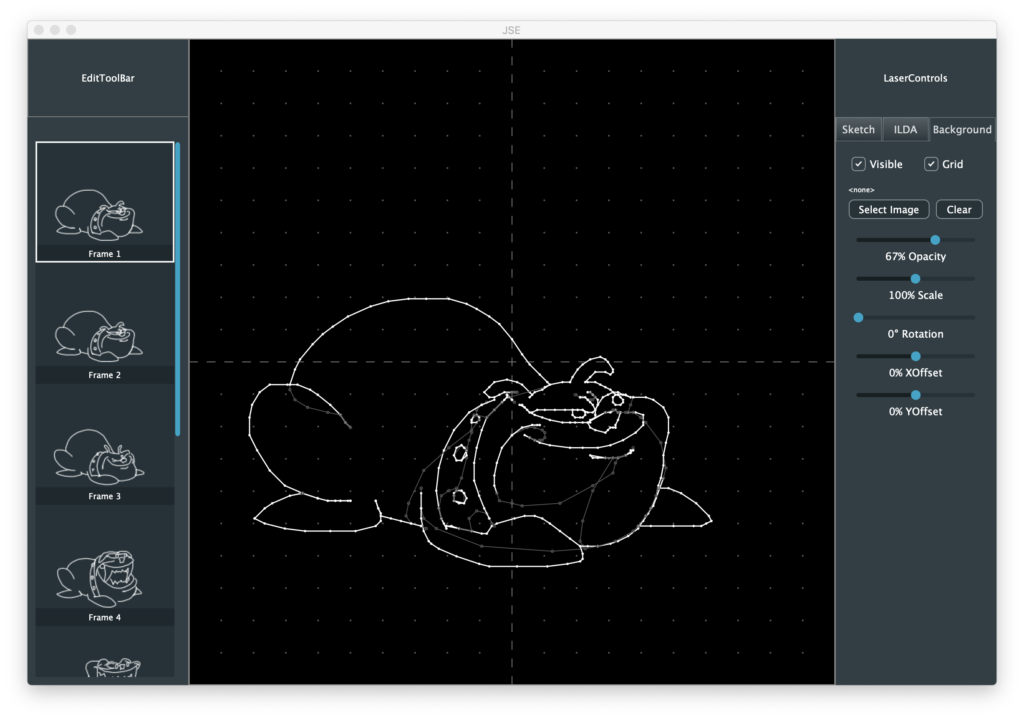
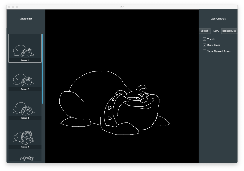
For those who have been following development, I did move a few things around and hide some under-construction areas for the release. To more quickly cover what is working, let’s open an existing .ild file to start. I’m using this one, created by the now defunct LaserMedia sometime in the late 1980s. Unfortunately I do not have the name of the original artist to credit. After selecting the File / Open menu and browsing to our file we should have this:
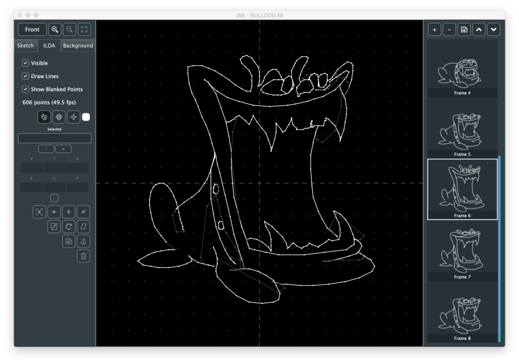
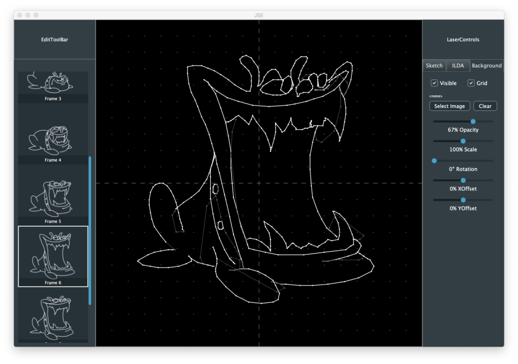
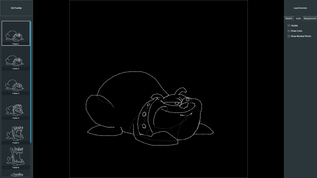
A nice little 8 frame animation of a bull dog ‘chomping’. The right edge is our frame management. The highlighted frame is the one we are editing. If we want to edit the ‘maximum chomp’ frame (#6), we just scroll down and click on it:
Note, I’ve tried to support modern pads and gestures wherever I can. You don’t actually have to click and drag the blue scroll bar, you can point at the list and either use the mouse scroll wheel, or the two finger scroll gesture on your touch pad.
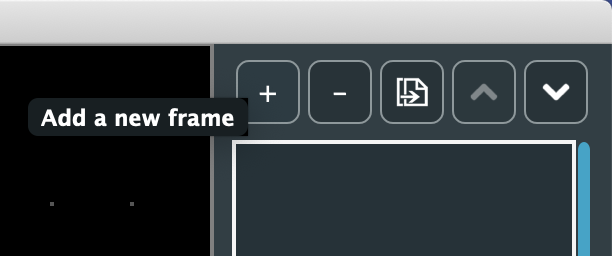
The buttons above the list are for frame management. From left to right, they are:
Insert a new frame after the currently selected one
Delete the currently selected frame
Duplicate the currently selected frame
Move the currently selected frame up in the frame order
Move the currently selected frame down in the frame order
Since my icon graphics skills are utter crap, it might not always be clear what a button or control does. No worries, just hover the mouse over it and some tip text should appear:
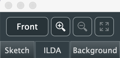
Moving over to the left side, the buttons on top here are for view control:
The top left button is for toggling viewing angle. ILDA is 3D format. That means that in addition to X (horizontal) and Y (vertical) information, each dot, or point, can have depth information. To see and edit that information we have to have different points of view. I’ll be adding more sophisticated 3D view support later, but for now clicking this button will toggle between three views:
Front
Bottom
Left
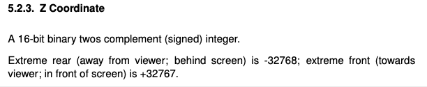
Yeah, I know, seems weird to use these three, but the ILDA spec calls out Z like this:
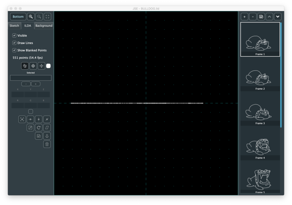
It’s a subtle thing, but the ILDA Z coordinates follow a different ‘thumb rule’ than ILDA X and Y. Since I don’t have good 3D view control and indicators yet, I picked the three views where up and right on our graph are always positive values and down and left are always negative values. YMMV but I found it too disorienting to have the polarity of things switch without more visual feedback. Anyway, the old graphic I’m using has no depth for any of the coordinates (all set to 0), so Bottom and Left are just lines of dots on one axis or the other:
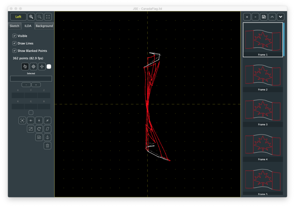
But other graphics, like this waving Canadian flag I found online, are more interesting:
Going back to our front view, the next 3 buttons are zoom in, zoom out, and Fit All. Zooming and panning is something ILDA editing involves a lot, so these buttons are just one of multiple ways to do it:
Keyboard Zoom/Pan
You can hold the <cmd>(Mac)/<ctrl>(Windows) button and press ‘+’, ‘-‘, or the arrows keys to zoom and pan.
Scroll Wheel Zoom/Pan
Scroll alone pans up and down. Hold <shift> to pan left and right. Hold <ctrl> to zoom in and out.
Touch Pad Zoom/Pan
Use two fingers to pan, pinch and spread to zoom.
However you do it, be forewarned that the bulldog’s face will haunt your dreams:
If you get zoomed in and lost, the Fit All button, or <cmd>(Mac)/<ctrl>(Windows> + ‘0’ will get you back to where we started.
The three tab button below the view controls select which layer we are working on. The Sketch layer currently does nothing (but will do quite a lot soon, I promise!).
The Background Layer controls the visible grid and allows you to add a reference image to edit against. We’ll come back to it later.
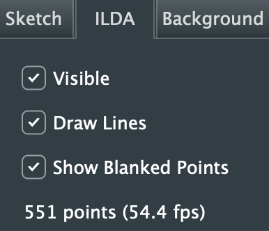
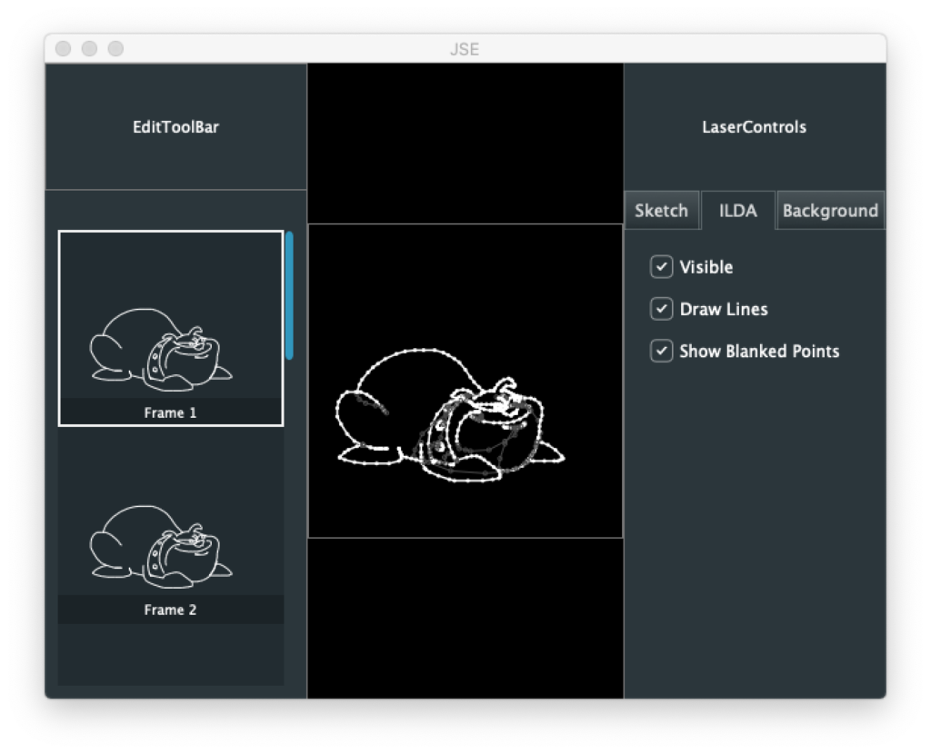
The ILDA Layer is the ILDA coordinate data, which we already have loaded, so let’s explore this layer first. The top section is, again, view control:
“Visible” controls the visibility of the whole layer
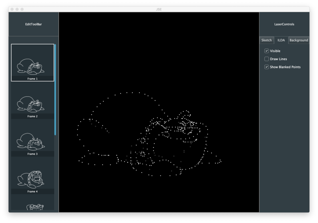
“Draw Lines” turns the connecting lines between points on and off
“Show Blanked Points” hides and reveals the parts of the image trace that are ‘blanked’ or invisible
Note: When blanked points are hidden they cannot be selected for editing, either with the different edit tools or the Select All menu option.
Below the three check boxes is a text indicator showing how many points are in the currently selected frame and what it’s frame rate would be at the current scan speed (fixed at 30 kHz in this release).
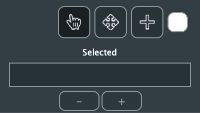
Next are our three primary tools and our our selected points display:
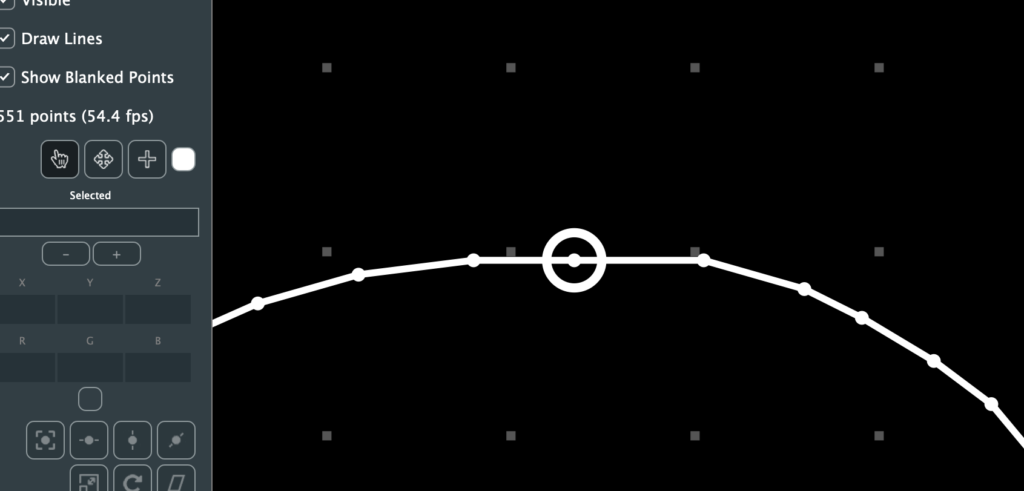
The hand is a ‘Selection Tool’, and is active by default. It is, as its name implies, meant to select points for manipulation. When it is active moving the mouse over a point on the screen will cause a circle to be drawn around it:
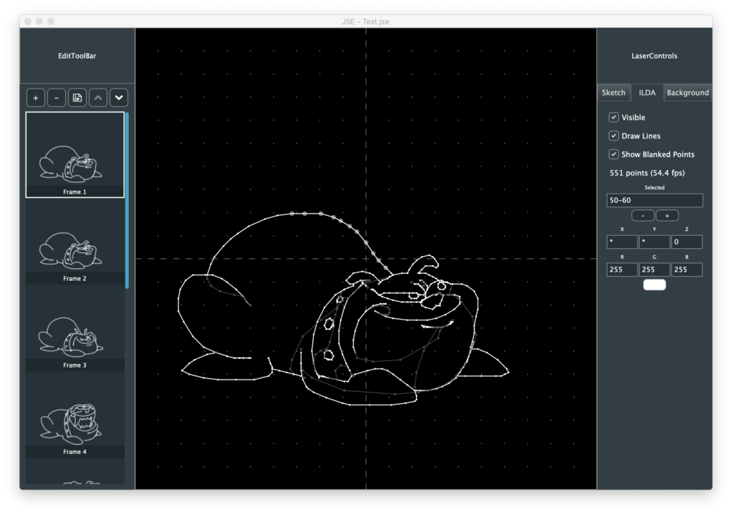
If you click the mouse the point will have a smaller circle fixed around it and the “Selected” field will show the point number:
A bunch of other stuff filled out and activated, but we’ll get to that in a moment. We can directly enter points to select as numbers in the selected field, and we can increment and decrement our selection with the – and + buttons below it (or the ‘[‘ and ‘]’ keys as a shortcut). This can be more useful than it sounds when you are exploring someone else’s ILDA file. For example, putting in ‘1’ to find the first point, then using the buttons or shortcut keys to see what order the image is traced out in.
The select tool can also select by clicking and dragging a rectangle around points. Holding down the <cmd>(Mac)/<ctrl>(Windows) lets you add to or toggle selections. Holding down the <alt> key lets you subtract from a selection:
The X, Y, Z, R, G, and B fields show the raw ILDA data for the selected point(s). You can edit a point with these fields, but it generally isn’t very useful. For example, in the case above, if I edit X to 0, all the points selected will jump to zero:
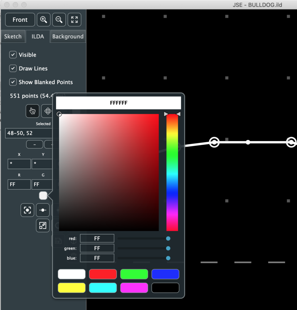
Likewise, it isn’t particularly convenient to convert colors into hex values in your head. An easier way to adjust color is to click on the small color swatch below the RGB values and use the popup color selector:
If you have a web color in mind you can type it in at the top. The hue and color boxes let you pick a color with the mouse. Slider bars are also available for direct control of R, G, and B. And there are color swatches at the bottom.
Note: Laser colors are a lot of work to fine tune, so the swatches are the RGB ‘all in colors’, plus black for blanking. You can dismiss the popup by clicking on the color swatch again, or any inactive part of the window.
To move our freshly colored points we can use the arrow keys on the keyboard.
The arrow keys alone move the points in fairly big steps. Holding the <shift> key makes the relative moves smaller/finer. Another way to move a selection is with the “Move” tool, next to the select tool.
If points are already selected, activate the move tool and then click and drag on the editor area. The selected points will move.
When you point the move tool at a single point, it will highlight and you can click and drag that point with one operation. This is meant for point by point cleanup once an image is sketched out.
However you move points, it is important to remember that you are moving relative to your currently selected viewing angle. If that is “Front”, your move will be X and Y. If one of the other views is selected, one direction of the move will be Z, or depth.
Below the color swatch are a number of operations you can perform on selected points (with more to come!):
The top 7 are pretty self explanatory. I’d suggest just trying Edit / Select All to pick all the points and play with them. The one thing worth mentioning is that the transforms, scaling, rotation, and skew, all have an option to control how they are centered. You can be centered on the selection:
This means the operation (in this case a Z rotation) is around the center of the selected points themselves. If you turn the check box off, the operation will be centered at 0,0, or the cross hair in the middle of the editing area:
Don’t let the explanation above confuse you. This is easy to understand if you rotate something off center, like the dog on the Z axis with each option and watch for yourself.
The next two selection operations are more laser-image specific. Duplicate creates and inserts an identical point right after the selected one. This is useful if you want to make hot spots in your images, like corners on a cube or beam dots.
The ‘Anchor’ button (yes, that’s what it is supposed to be) is similar. It puts a blanked (invisible) point before the selected one(s), at the same location. This is useful if you are getting scanner movement artifacts at a laser off->on transition when your graphic is projected.
The trash can, of course, deletes the selected points. You can also delete with <delete> or <backspace>.
This leaves the Point Insertion Tool next to the move tool. It was actually created for modifying existing ILDA frames, but while the Sketch layer is under construction, let’s create a simple animation with it.
First, File / New to get us back to a blank canvas. Make sure that the “Front” view is selected:
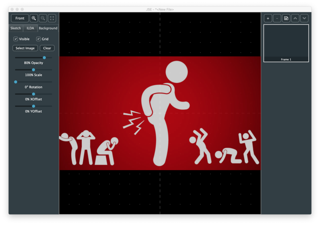
I am going to want to trace against an existing image, so I next select the “Background” tab and click the “Select Image” button. The first simple image I found was this one:
Alas, I have no idea who created this fabulous international symbol for butthurt. I tried images.google.com for a reverse search to no avail. But it is perfect for our purposes. I like to see the grid, so I turned the opacity of the image down a bit. Normally, you want to use as much of the ILDA area as you can, so there are also scale, position, and rotation options, but I’m just doing something down and dirty, so I’ll stop here.
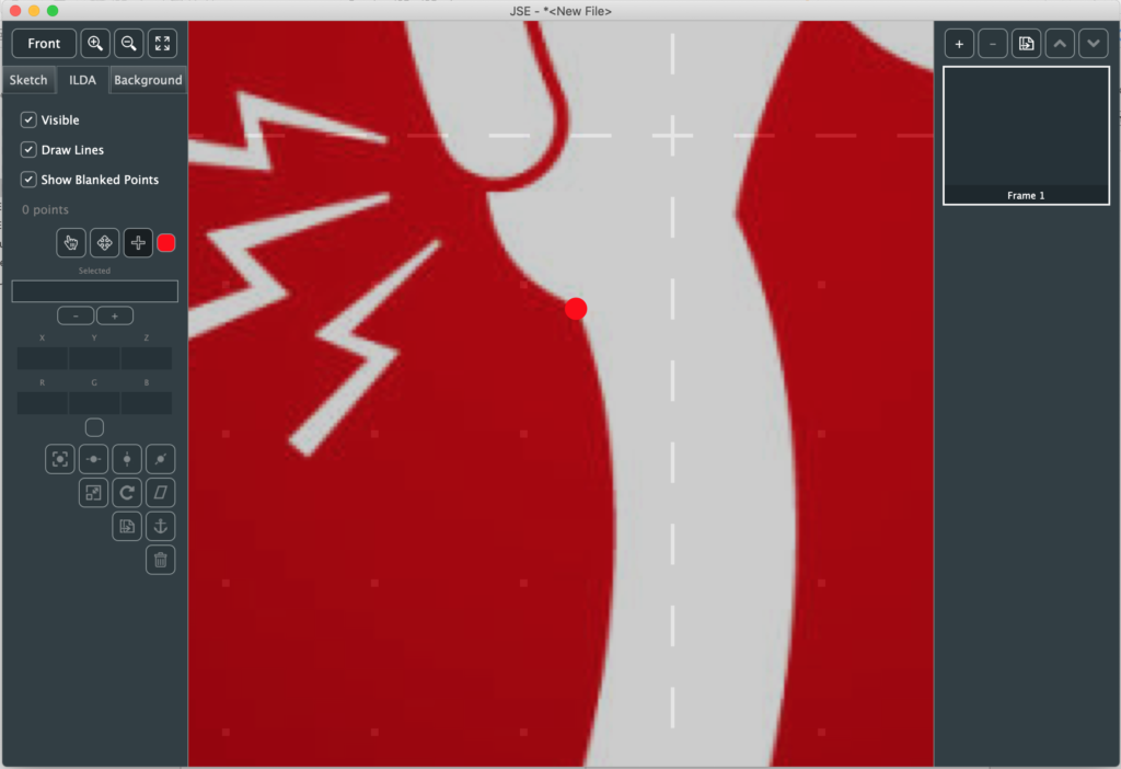
Next I go back to the ILDA layer, zoom in a bit, select the “Point Insertion Tool”, and use the color swatch next to it to select red. Now I am dragging a red dot around the screen (under a cross hair cursor you can’t see in the screenshot):
I put the dot at an indiscrete spot over the image and just start clicking along the outline of the body:
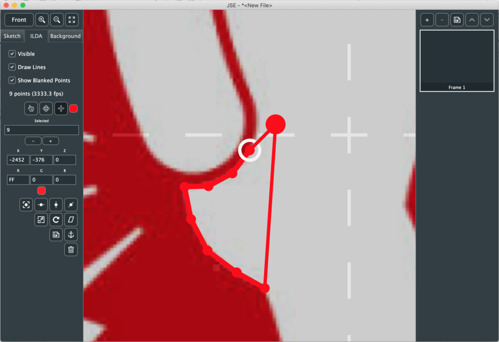
As I click to add each point, it becomes the currently selected, so I can tweak its position in small steps with <shift> + the arrow keys.
If I get to a sharp turn and know I want to put extra points at that position, I can hold the <ctrl> key and the dot will snap to an existing point if it is near one.
Although it isn’t useful here, you can also hold the shift key and the dot will snap to the nearest 45 degree angle (0, 45, 90, etc.) from the last point.
I tend to use the mouse and scroll wheel to zoom and pan as I go (yes, I’m thinking about an auto pan feature), but you can adjust the view however you like (dragging the dot off to the edge of the edit field to use the menu or a tool bar button looks weird, but won’t hurt anything).
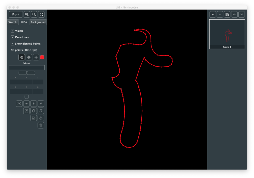
As I finish outlining the body, I <ctrl> click to snap to the starting point and hit <ESC> (which deselects all points):
I’ve turned the Background Layer off to make it easier to see. Now I need to decide where to break off and draw other items, for example, the head.
I could go over and use the color selector by the Point Insertion Tool to select black to make the invisible line, but instead I used the shortcut ‘B’, which toggles between blanked and the last non blanked color. Similarly, ‘C’ rotates between the 7 non blanked standard swatch colors (these shortcuts are shown in the Edit menu when this tool is selected if you forget).
Still using the point insertion tool, the highlight circle above shows me the point I am going to insert immediately after if I click. Once I click I get a dot and can place it wherever I want:
However, in a case like this, trying to make an invisible line from one section to the next, the first thing we are usually going to do is hold <ctrl> and put a point in the new color (in this case blanked) at the point we just selected, so there is a shortcut. Holding <alt> while you click will do that first step for you. That is, you auto inserted a point where you highlighted and the dot represents your second point in the new color:
If you drop a point by mistake you can always delete it with <del> or <backspace>, or use the Undo feature (<cmd>(Mac)/<ctrl>(Windows) + ‘z’). I rushed a bit and ended up with this:
Normally this is where you might turn on the laser output and use the move, duplicate, anchor, etc. features to clean the image up, but I haven’t written that yet, so I just adjusted a few points by eye.
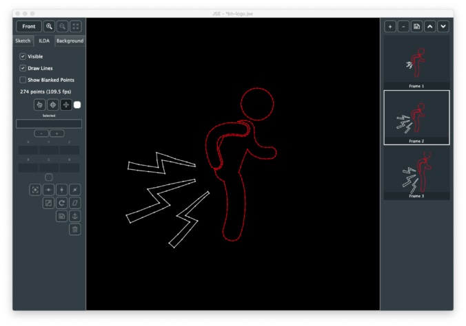
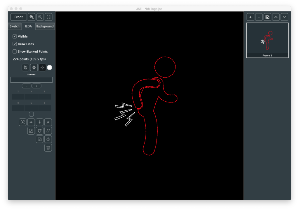
Next I duplicated the frame, turned “show blanked points” off, selected the lightning bolts, and scaled and positioned them:
Last, I made blanking visible again and moved those points a bit and dropped a few additional points on the larger lighting bolts.
We can save the file to a .jse file (our own format that includes meta data, like the background image). Or we can use File / Export ILDA File to generate a .ild file.
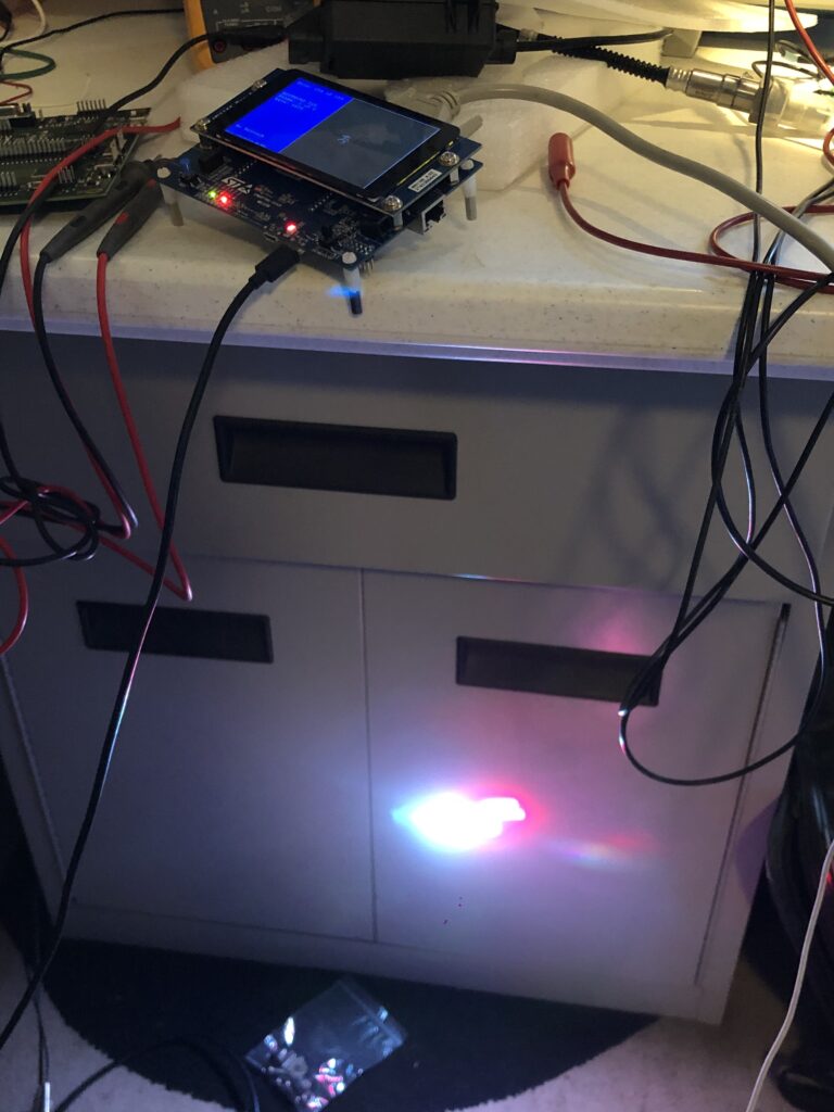
Honestly, my expectations were pretty low. Whenever I’ve made something for lasers in the past I’ve spent a lot of time tweaking and editing points, but scanners have gotten a better and this is all pretty simple shapes. I wish I was better at photographing lasers:
Because this turned out a lot funnier than I expected. I’m thinking about projecting it on the side of my house for the rest of 2020, tbh:
Maybe animate the lighting bolts in color… Anyway, no, JSE isn’t a proper creation tool yet, but this is just the first Alpha! I promise, more good things to come soon. And, rest assured, your comments, suggestions, even angry tirades about anatomically impossible sex acts I should conduct with a diode laser because my editor is so stupid, are all appreciated!
Last time we talked about starting to manipulate ILDA data. But before we manipulate points on the ILDA layer we need to have a mechanism to keep track of a ‘selection’, or which points we want to modify.
There are several different common ways to do this but I went ahead and just repurposed JUCE’s SparseSet class. At first glance, it might not seem obvious why. Given the relatively modest numbers of points that we will generally have selected in a frame we could just use a container, like JUCE’s Array class. Or one of the Standard Template Library container classes. Just make an array of uint16 values (the maximum number of ILDA points in a frame) and add the index of each selected point to it.
The downside to this is testing if a given point is selected when we are doing something like drawing all the points to the screen. If our selection is big, we can spend a lot of processor time walking through the array looking to see if it contains a given index.
There are ways to optimize this, like keeping our array sorted in numerical order. But what we really want is some sort of a quickly searchable hash table like mechanism. As luck would have it, that is precisely what a SparseSet already is. It doesn’t keep and array of individual values, it keeps an array of ranges. Each range has a start and a length. So if we have 60 points selected starting at index 100, we don’t store 100, 101, 102… But just start 100, length 60.
This makes testing to see if a specific point is in the overall set very efficient. Further, the class is smart about optimizing ranges when they are added. If we add 100-120 and 110-140, the class doesn’t just keep both ranges and test against them. It detects overlaps and optimizes them into a single range (in this case 100-140).
I actually went ahead and exposed the SparseSet used for ILDA point selection to the user in an edit box. I tweak a little so the user sees base 1 indexes instead of the base 0 indexes we use internally, but you can play directly and see how SparseSet operates.
Putting in a single value, selects that point:
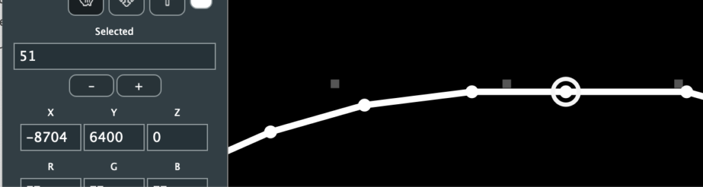
We’ll get into mouse manipulations in the next post. For now, just look at the property values shown for selected point 50. We can enter a new XYZ position and color in the edit fields:
The scanners might not like the big jump above but, thanks to what we added last time, we can always undo. But we can also type in a range using ‘-‘:
Like single points, we can shift that range up or down with the – and + buttons below the text box:
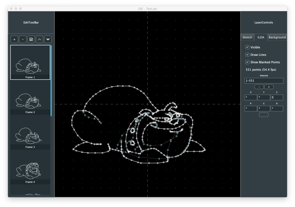
I added the command/ctrl A (select all) and command/ctrl D (deselect all) shortcuts to the menu and you can see that select all just makes a single, all inclusive, range in this case:
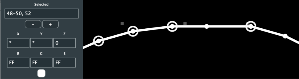
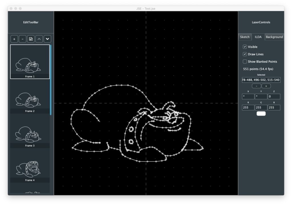
But look what happens if we turn off “Show Blanked Points” and hit command/ctrl A again:
The selection field now shows a list of ranges, separated with commas. Obviously the user won’t normally want to type these values in themselves, they’ll want to use a selection tool, or shortcuts like select-all. But it can be occasionally useful and you can experiment typing in ranges and see how the SparseSet class optimizes them.
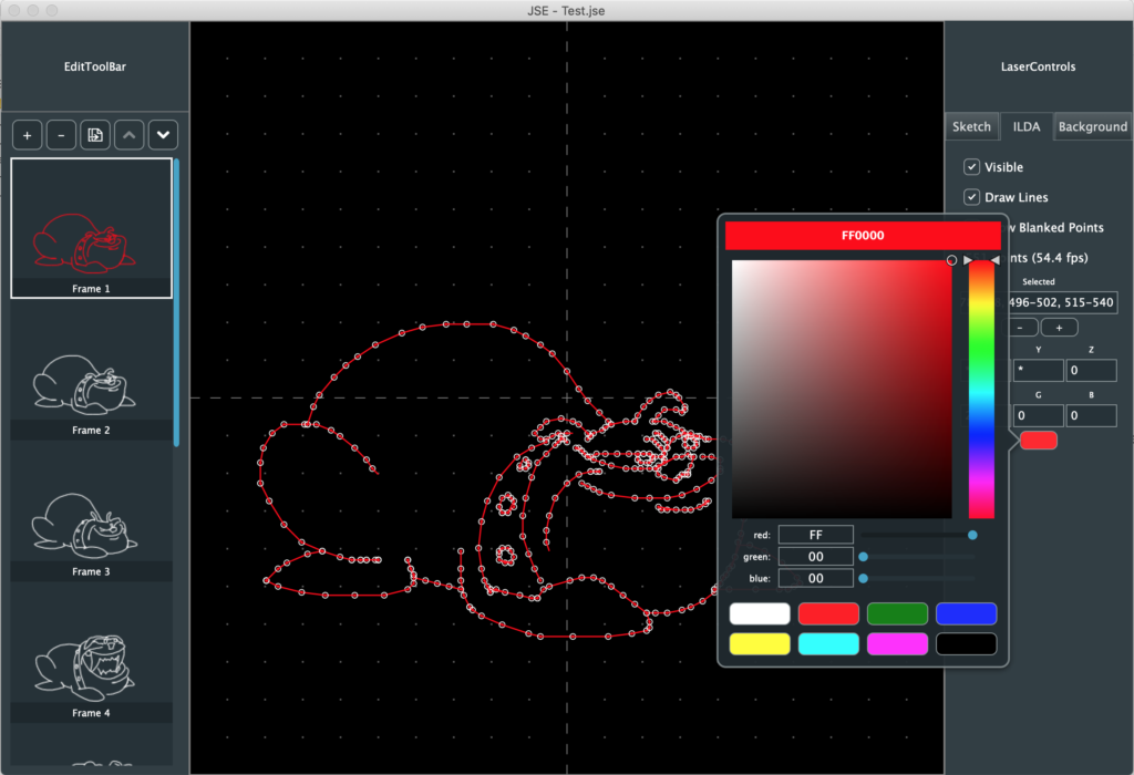
Since we have all the visible points selected, let’s go ahead and color them by clicking the swatch below the RGB edit fields:
JUCE has an ok color selection class called ColourSelector. You can enter web colours by typing them at the swatch at the top, use the mouse with the hue slider and color field in the middle, or use the sliders and RGB values at the bottom. The class has it’s own color swatch scheme, but it’s weird. A menu pops up every time you clock on a swatch asking if you want to use or save. So I disabled that and just put my own eight fixed color swatches at the bottom, with the seven traditional laser colors and black for blanking.
There is some other housekeeping worth mentioning. As I covered last time, our frames are “reference counted objects”, so can can keep them around for undo and discard them pretty freely. This made it very straight forward to add some basic frame operations to the Edit menu and a button bar across the top of the frame list:
You can add new frames, delete frames, duplicate frames, and shift a frame up and down in the order. We’ll get fancier later but this is a start.
Most other housekeeping is related to files. In addition to the ILDA import we looked at last time, you can now export your edits back to ILDA format files as well. Because we only write one of the 5 ILDA formats, the export function is very straightforward:
bool IldaExporter::save (ReferenceCountedArray<Frame>& frameArray, File& file)
{
    if (file.exists())
        file.deleteFile();

    FileOutputStream output (file);

    if (! output.openedOk())
        return false;

    ILDA_HEADER header;
    zerostruct (header);

    header.ilda[0] = 'I'; header.ilda[1] = 'L';
    header.ilda[2] = 'D'; header.ilda[3] =  'A';
    memcpy (header.name, "Scrootch", 8);
    memcpy (header.company, ".me! JSE", 8);
    header.format = 4;
    int s = frameArray.size();
    header.totalFrames.b[0] = (uint8)(s >> 8);
    header.totalFrames.b[1] = (uint8)(s & 0xFF);
    header.projector = 1;

    for (auto n = 0; n < frameArray.size(); ++n)
    {
        // Update header
        header.frameNumber.b[0] = (uint8)(n >> 8);
        header.frameNumber.b[1] = (uint8)(n & 0xFF);

        if (frameArray[n]->getPointCount())
        {
            header.numRecords.b[0] = (uint8)(frameArray[n]->getPointCount() >> 8);
            header.numRecords.b[1] = (uint8)(frameArray[n]->getPointCount() & 0xFF);
        }
        else
        {
            header.numRecords.b[0] = 0;
            header.numRecords.b[1] = 4;
        }

        // Write Header
        output.write (&header, sizeof(header));

        Frame::XYPoint point;

        // Now records
        if (frameArray[n]->getPointCount())
        {
            for (uint16 i = 0; i < frameArray[n]->getPointCount(); ++i)
            {
                Frame::XYPoint in;

                frameArray[n]->getPoint (i, in);

                // Swap endian order of X, Y, and Z
                point.x.b[0] = in.x.b[1];
                point.x.b[1] = in.x.b[0];
                point.y.b[0] = in.y.b[1];
                point.y.b[1] = in.y.b[0];
                point.z.b[0] = in.z.b[1];
                point.z.b[1] = in.z.b[0];
                point.red = in.red;
                point.green = in.green;
                point.blue = in.blue;
                point.status = in.status;
                if (i == (frameArray[n]->getPointCount() - 1))
                    point.status |= ILDA_LAST;

                output.write (&point, sizeof(point));
            }
        }
        else
        {
            // Write out 4 blanked points
            zerostruct (point);
            point.status = ILDA_BLANK;
            output.write (&point, sizeof(point));
            output.write (&point, sizeof(point));
            output.write (&point, sizeof(point));
            point.status = ILDA_BLANK | ILDA_LAST;
            output.write (&point, sizeof(point));
        }
    }

    // One more header without records
    // We don't care about endian swap for this
    header.frameNumber.w = header.totalFrames.w;
    header.numRecords.w = 0;

    output.write (&header, sizeof (header));
    output.flush();

    return true;
}
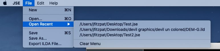
I got sick of browsing for the same files all the time so I added a persistent “Open Recent” list sooner than I anticipated:
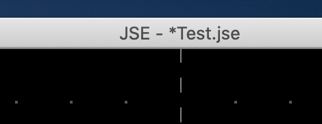
This was actually pretty trivial using the PropertiesFile and RecentlyOpenedFilesList classes from JUCE. I also added a ‘dirty’ counter to keep track of if a file has been edited since it was last saved. When dirty is not zero, an ‘*’ is added to the file name at the top of the window:
I decided on a counter instead of a simple flag because I think it works better with undo/redo. If you roll a file back to point you opened it, the count returns to 0. Redo and the count starts incrementing again.
Last, but not least, I bit the bullet and did the .jse specific file load and save. Just to recap, we use our own file format to keep things like background reference images and the sketch layer for each frame. That part is still true. Pretty much everything else I wrote last time is now false.
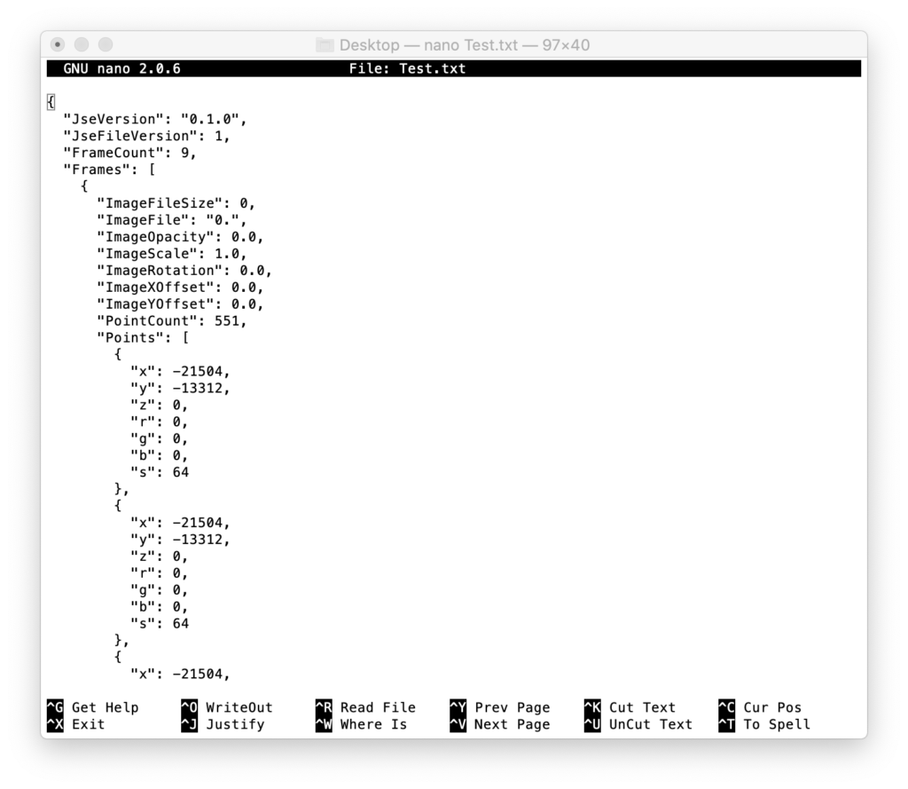
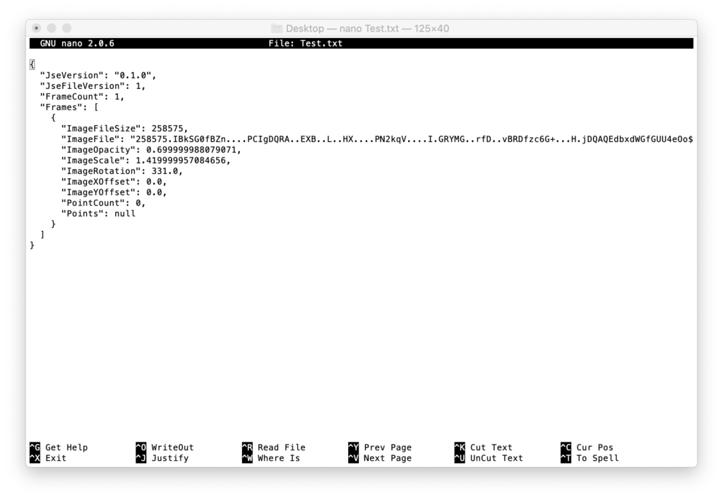
First, I started with XML, hated it, and switched to encoding the information as a ‘named property JSON text file’. JSON is ‘Java Script Object Notation‘. It’s actually pretty simple and easy to read. JUCE’s JSON support allows you to export with indent formatting, and I do, so if you open the data with a text editor it looks pretty comprehensible:
You can see a little info at the top of the file, then the first of the 9 frames. Each ILDA coordinate is in plain text for x, y, z, r, g, b, and s (status byte). The downside is storing points this way is huge. Our whole file is 800 kbytes in size! The same animation in ILDA binary format is 38 kbytes.
Enter the GZIPCompressorOutputStream and GZIPCompressorInputStream classes in JUCE. They use something called zlib. It is a free, open source, liberally licensed compression/decompression library. And it was super easy to add to our new JSEFileLoader and JSEFileSaver helper classes, for example:
bool JSEFileSaver::save (FrameEditor* editor, File& file)
{
    frameEditor = editor;
    DynamicObject::Ptr fileObj = new DynamicObject();

    fileObj->setProperty (JSEFile::AppVersion, ProjectInfo::versionString);
    fileObj->setProperty (JSEFile::FileVersion, JSE_FILE_VERSION);
    fileObj->setProperty (JSEFile::FrameCount, frameEditor->getFrameCount());

    var frames;
    for (uint16 n = 0; n < frameEditor->getFrameCount(); ++n)
        frames.append (frameToObj (n));

    fileObj->setProperty (JSEFile::Frames, frames);

    var json (fileObj.get());

    if (file.exists())
        file.deleteFile();

    FileOutputStream output(file);
    if (output.openedOk())
    {
        GZIPCompressorOutputStream z (output);
        JSON::writeToStream(z, json);
        z.flush();
        output.flush();
        return true;
    }

    return false;
}
All the compression magic is in two lines. The original line was:
JSON::writeToStream(output, json);
Making it two lines compressed the output file:
        GZIPCompressorOutputStream z (output);
        JSON::writeToStream(z, json);
And did zlib do the trick! Our 800 kbyte file saves as 22 kbytes. This is smaller than the binary ILDA original! That I did not expect. If you want to examine the text contents of a file for some reason you don’t have to alter the code and save again from our editor. There are a number of zlib friendly tools floating around. I used the command line application “openssl“. OpenSSL got a bit of a bad wrap over some security problems, but it is still installed for use with git and some other tools on both my OS X and Windows partitions. Decompressing a .jse file with opensll looks something like this:
openssl zlib -d -in Test.jse > Test.txt
The app is followed by the “zlib” command, “-d” for decode, “-in Test.jse” to specify the input file, then “> Test.txt” directs the decoded output to a file instead of the screen.
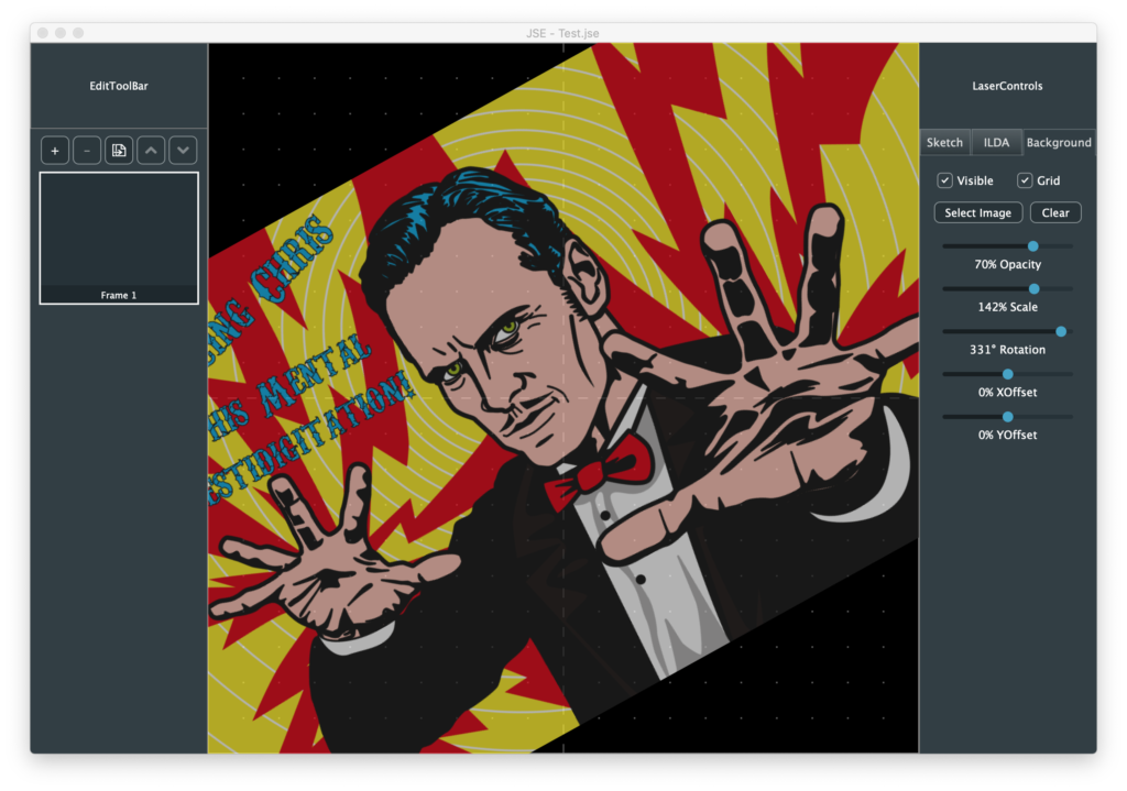
One other thing I changed my mind about was background images. Last time I said I was only going to keep references to the media. But I didn’t like that user experience. You have to remember to send the files together, give the user some way to restore links, etc. So I just bit the bullet and embedded any background images in the .jse file:
This saved in a JSE file that looks like this:
The original image file used is encoded as a very long base64 style string. It’s worth noting that JSE files don’t have to have any ILDA points. You can save the project when it is still just reference images and sketches. But ILDA files must have points, otherwise it is assumed that the zero point frame is the last in the file. If you export a frame to ILDA that does not yet have any points in it, they export function listed above does this:
And writes out 4 dummy blanked points at 0,0 (center). I’m trying to get reasonable pre-alpha version out for people to start playing with this week, but I’ll try to write up more details again soon!
Last time we covered the critical question of maintaining a scaled editing area so that we can work on a 16 bit resolution ILDA file on lower resolution screens. As I mentioned in that post, one of the other areas we want to address sooner rather than later is ‘undo’/’redo’. All modern editors are expected to do this well and users have become accustomed to relying on the feature.
Instead of starting from scratch, our good friend JUCE has an UndoManager class. It is a specialized container class that holds instances of an UndoableAction class. One of the things I like about this setup is you add UndoableAction instances to the manager by “performing” them. That is, the operation is ‘done’ initially by exactly the same code that will be executed for a ‘redo’ operation. This eliminates a common pitfall with undo/redo systems bolted on after the fact, where do and redo are different bodies of code that don’t always stay in perfect sync.
Up to now our FrameEditor worker class has basically had public get and set functions. For example, from FrameEditor.h:
The function _setRefOpacity is just our original setRefOpacity function renamed. This is our “destructive” version of the operation. Our new setRefOpacity function is the undoable version, the one regular clients call. Instead of calling _setRefOpacity directly, it creates an instance of this class and performs it with the UndoManager derived class:
When the class is instantiated it saves the desired new value and a pointer to our FrameEditor worker class. The perform() method saves the old (current) value and sets the new one, using the destructive _setRefOpacity. Undo uses the same function to set the old, preserved value.
One concern with a scheme like this is the scope, or life, of objects. We have an instance of this undoable object class that points to our FrameEditor class. We want to make sure that we never get into a situation where we try to ‘undo’ something after our FrameEditor has already been deleted. I chose to elliminate this possibility by making our FrameEditor and the UndoManager the same object. FrameEditor “inherits” from UndoManager:
class FrameEditor  : public ActionBroadcaster,
                     public UndoManager
In various object oriented programming paradigms, this is called the “Is-A” vs “Has-A” question. Or, “the entity relationship model”, if you want to sound even more obnoxious. To me it just made sense that our FrameEditor worker class, which we can now ask to perform undoable operations, is the same object we use to undo them.
But, regardless, either having our FrameEditor be an UndoManager or have an UndoManager as a member variable solves our scope problem. The scope, or object life, of our worker class, the UndoManager, and any saved UndoableAction classes that point back to our worker class, are all tied together.
With the Is-A approach, our undoable set function looks something like this:
We make sure the caller isn’t passing in an out-of-range value, check if the request actually changes anything, and, if yes, create and perform the UndoableAction class we defined for this operation (automatically saving it into the UndoManager maintained list).
This works, but we run into one headache. If we grab the opacity slider and play with it, we get a zillion of these events stacked up to undo. Generally, that’s not what the user expects. They have a starting opacity, fiddled with the slider, then stopped. From their point of view, all that fiddling is just one undoable adjustment.
The JUCE UndoManager has a mechanism called “Transactions”, meant to lump multiple UndoableActions into a single undo/redo operation. But it also has a nice rollback feature, which helps us here:
void FrameEditor::setRefOpacity (float opacity)
{
    if (opacity < 0)
        opacity = 0;
    else if (opacity > 1.0)
        opacity = 1.0;

    if (opacity != refOpacity)
    {
        if (getCurrentTransactionName() == "Background Opacity")
            undoCurrentTransactionOnly();

        beginNewTransaction ("Background Opacity");
        perform(new UndoableSetRefAlpha (this, opacity));
    }
}
If we are doing a series of opacity changes, we keep rolling back the transaction to our original value, then adjust to the new one. This turns slider fiddling into a single undo/redo step.
At this point our background layer looks a lot like last time:
I added a button to clear (delete) the background image and reference grid you can turn on and off, but the big difference is that we can now undo and redo all the adjustments you make:
Now that we have a scheme for undo/redo and a way to scale, draw, and interact with ILDA resolution data, it is time to open some!
The ILDA image exchange format is pretty bare bones. It doesn’t have a mechanism to include vendor specific information. So we will need a to support two formats for opening:
ILDA (.ild) files
JSE (.jse) files
A JSE file will contain all the ILDA information, plus all the other items we are tacking on, like our reference (background) and sketch layers. For the time being I’ve decided not to embed any selected background images, thumbnails, etc. in our JSE file. Background images will be kept as a media reference (file name/location), and thumbnails will be reconstructed at load time.
Without raster graphics content, storing coordinates, sketch objects, etc. as ASCII text seems fine to me. JUCE has great support for reading and creating XML files, so we’ll start there. This should make our files easy to examine and fiddle with by eye in a normal text editor. If file sizes becomes an issue we could use JUCE’s wrappers for zlib to compress our XML files in the GNU zip format.
But first things first, let’s just parse an ILDA file and put it into one or more Frame objects for us to manipulate with our FrameEditor helper class!
The ILDA load function in IldaLoader.cpp looks a lot like our ILDA code in our scan system firmware:
bool IldaLoader::load (ReferenceCountedArray<Frame>& frameArray, File& file)
{
    FileInputStream input (file);
    if (input.failedToOpen())
        return false;

    frameArray.clear();

    // Loop until we are out of frames
    do
    {
        Frame::Ptr frame = new Frame;

        ILDA_HEADER header;

        // Read the header
        if (input.read (&header, sizeof(header)) != sizeof(header)) break;

        // Valid?
        if (header.ilda[0] != 'I' || header.ilda[1] != 'L'
                || header.ilda[2] != 'D' || header.ilda[3] != 'A') break;

        uint16 rCount;
        rCount = header.numRecords.b[0];
        rCount <<= 8;
        rCount += header.numRecords.b[1];

        // 0 records marks end
        if (!rCount) break;

        int n;
        for (n = 0; n < rCount; ++n)
        {
            Frame::XYPoint newPoint;

            // We have 5 different handlers for the 5 different
            // ILDA data formats (ugh)
            if (header.format == 0)
            {
                ILDA_FORMAT_0 in;

                // Try to read the next point
                if (input.read (&in, sizeof(in)) != sizeof(in)) break;

                // Change endian and store X, Y and Z
                newPoint.x.b[1] = in.x.b[0];
                newPoint.x.b[0] = in.x.b[1];
                newPoint.y.b[1] = in.y.b[0];
                newPoint.y.b[0] = in.y.b[1];
                newPoint.z.b[1] = in.z.b[0];
                newPoint.z.b[0] = in.z.b[1];

                // Store status (minus last frame indicator!)
                newPoint.status = (in.status & 0x7F);

                // Lookup and store colors
                newPoint.red = IldaColors[in.colorIdx].red;
                newPoint.green = IldaColors[in.colorIdx].green;
                newPoint.blue = IldaColors[in.colorIdx].blue;
            }
            else if (header.format == 1)
            {
                ILDA_FORMAT_1 in1;

                // Try to read the next point
                if (input.read (&in1, sizeof(in1)) != sizeof(in1)) break;

                // Change endian and store X, Y and Z
                newPoint.x.b[1] = in1.x.b[0];
                newPoint.x.b[0] = in1.x.b[1];
                newPoint.y.b[1] = in1.y.b[0];
                newPoint.y.b[0] = in1.y.b[1];

                newPoint.z.w = 0;

                // Store status (minus last frame indicator!)
                newPoint.status = (in1.status & 0x7F);

                // Lookup and store colors
                newPoint.red = IldaColors[in1.colorIdx].red;
                newPoint.green = IldaColors[in1.colorIdx].green;
                newPoint.blue = IldaColors[in1.colorIdx].blue;
            }
            else if (header.format == 2)
            {
                // Color Palette
                ILDA_FORMAT_2 in2;
                // Try to read the next point
                if (input.read (&in2, sizeof(in2)) != sizeof(in2)) break;
            }
            else if (header.format == 4)
            {
                ILDA_FORMAT_4 in4;

                // Try to read the next point
                if (input.read (&in4, sizeof(in4)) != sizeof(in4)) break;

                // Change endian and store X, Y and Z
                newPoint.x.b[1] = in4.x.b[0];
                newPoint.x.b[0] = in4.x.b[1];
                newPoint.y.b[1] = in4.y.b[0];
                newPoint.y.b[0] = in4.y.b[1];
                newPoint.z.b[1] = in4.z.b[0];
                newPoint.z.b[0] = in4.z.b[1];

                // Store status (minus last frame indicator!)
                newPoint.status = (in4.status & 0x7F);

                // Store colors
                newPoint.red = in4.red;
                newPoint.green = in4.green;
                newPoint.blue = in4.blue;
            }
            else if (header.format == 5)
            {
                ILDA_FORMAT_5 in5;

                // Try to read the next point
                if (input.read (&in5, sizeof(in5)) != sizeof(in5)) break;

                // Change endian and store X, Y and Z
                newPoint.x.b[1] = in5.x.b[0];
                newPoint.x.b[0] = in5.x.b[1];
                newPoint.y.b[1] = in5.y.b[0];
                newPoint.y.b[0] = in5.y.b[1];

                newPoint.z.w = 0;

                // Store status (minus last frame indicator!)
                newPoint.status = (in5.status & 0x7F);

                // Store colors
                newPoint.red = in5.red;
                newPoint.green = in5.green;
                newPoint.blue = in5.blue;
            }
            else
                break;

            // Store the point
            frame->addPoint (newPoint);
        }

        if (n != rCount) break;

        // Don't store palettes!
        if (header.format != 2)
        {
            frame->buildThumbNail();
            frameArray.add (frame);
        }
    }
    while (1);

    if (frameArray.size())
        return true;

    return false;
}
All read coordinates are converted into 16 bit X, Y, and Z data with truecolor (8 bits R, G, and B) data. If you look at frame.h, the Frame::XYPoint data type is just the ILDA_FORMAT_4 under a different name:
If you skim the code above, a few things might stand out. First, we ignore custom palettes. If a file uses indexed colors, you get the ILDA standard palette. If this turns out to be a real problem, it wouldn’t be hard to fix. I am just reluctant to code something that I don’t even have a suitable sample file to test with!
Another thing that might catch your eye is that we discard the “LastPoint” status bit. We don’t need it in the editor, we keep all the coordinates for a Frame in a juce::Array container class:
Array<XYPoint> framePoints;
This way, we can copy, paste, and reorder at will without worrying about keeping the flag in the right spot. We just have to be sure to add it back in when we export our point array to an ILDA file!
The code above also might look like it leaks memory. We allocate a new Frame class with “new” at the top of every iteration of our do loop:
    // Loop until we are out of frames
    do
    {
        Frame::Ptr frame = new Frame;
But we never delete it and only conditionally add it to the frame array that the caller passed in. This is a variation on RAII techniques we discussed before with std::unique_ptr and juce::ScopedPointer.
Those classes delete what they point to when they go out of scope, which isn’t what we want here. Just as FrameEditor “Is-A” UndoManager above, every instance of the Frame class now “Is-A” ReferenceCountedObject:
class Frame : public ReferenceCountedObject
These are pretty much what the name implies. The class has a counter. When the counter is decremented to zero, the object is deleted. When our object is created, we put it in a special kind of Pointer class called “Frame::Ptr”. This is just shorthand for the long winded:
ReferenceCountedObjectPtr<Frame>;
This incremented our count from 0 to 1. IF we add it to the frame array, which you can see is a long winded reference counting version too:
ReferenceCountedArray<Frame>& frameArray
The count is incremented from 1 to 2. The next time we assign a new pointer at the top of the do loop, the previous object is decremented (2 to 1 if saved, 1 to 0 and deleted if not). Similarly, when our function ends, any object in the pointer is decremented and conditionally deleted when the pointer class itself is destroyed.
We didn’t have to use reference counted objects just for our ILDA loader. The std::unique_ptr class has a release() method specifically to transfer ownership of a pointer to another container. But reference counted Frame objects are also useful for undo/redo. Instead of making fresh copies of every frame we delete, etc., we can just hand off the pointer to the UndoableAction class variant and release our reference count on it. Whenever the UndoManager releases the UndoableAction class, the reference will be again decremented and, unless it is still referenced by other instances of undo operations, deleted.
In addition to an ILDA file loader, I added a helper to build thumbnail images, which the loader indirectly invokes for each frame saved:
        // Don't store palettes!
        if (header.format != 2)
        {
            frame->buildThumbNail();
            frameArray.add (frame);
        }
I then modified the FrameList component so that it “Is-A” ListBoxModel, for a ListBox added to it. We are going to have to make our own specialized version of ListBox later when we add advanced Frame operations, but this at least gives us a way to preview and select Frames now:
I actually made the generated thumbnails have transparent backgrounds and made the frame labels a semi transparent bar over the main working area. I wanted the thumbnails to be useful without being too visually distracting. Particularly when an image is in color:
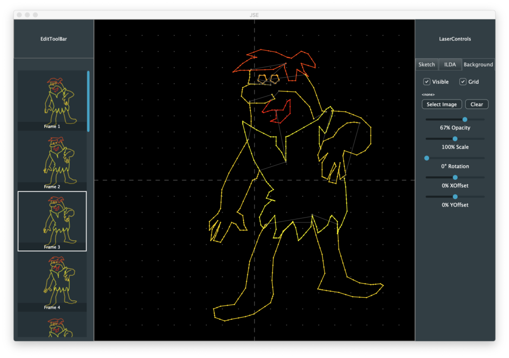
And, believe it or not, this Barney animation is even worse when you project it. But it’s better than anything I have ever drawn, is colorized, and Hanna Barbara likely won’t sue me, so… here it is.
Anyway, I also added some controls for ILDA layer display. Here is with the reference layer grid turned off:
You can turn off the blanked points:
Or hide the point to point connecting lines:
It’s worth reiterated that this is being drawn in our WorkingArea component at full ILDA resolution. The only math we do for coordinates is the arithmetic to shift from center 0,0 to top left 0,0:
This is great for maintaining registration of everything we draw, etc. but what about our circle, dot, and line sizes? We want those to relate back to something that makes sense to the user on the screen, not ILDA resolution. For now I scale them to a target number of pixels on the display:
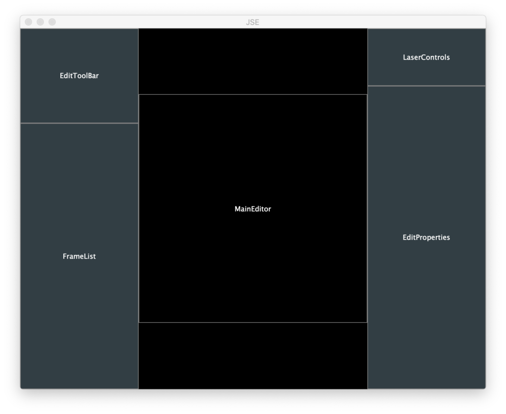
This makes things look at little thick when we make the window really small:
And a little thin when we maximize on a big monitor:
But it is a good starting point. We can add a 2nd order proportional adjustment later. After we spend some time editing content. Speaking of which, next stop, let’s start selecting and editing ILDA content and get our Sketch layer going!
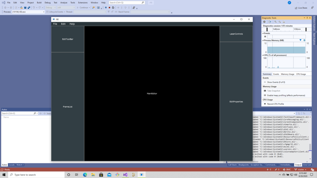
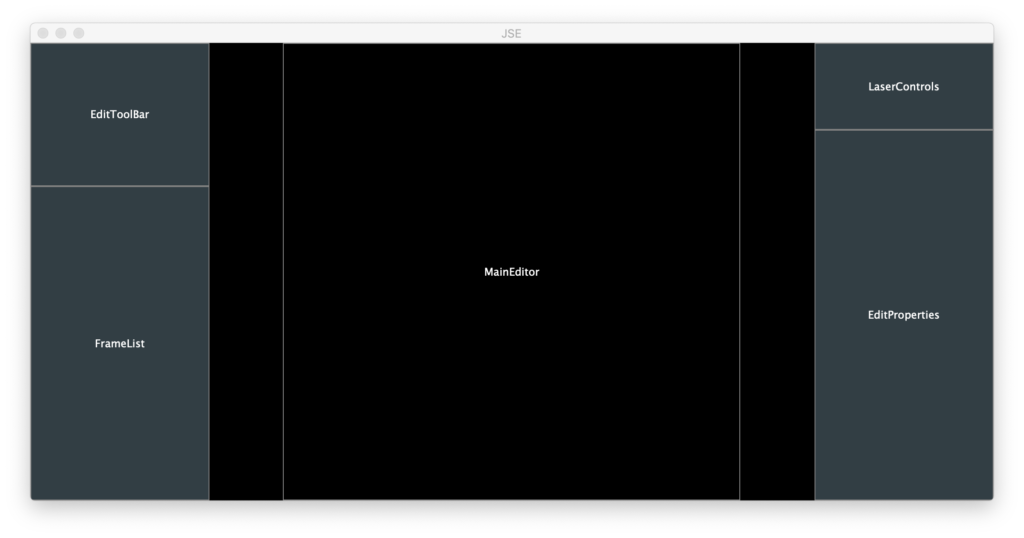
Last time we created a simple skeleton and populated it with placeholder JUCE components. It’s nice that it built on multiple platforms, but we still have a lot to add to all those empty squares:
With JUCE, as you will see in a bit, it is easy to get quite a lot happening in short order. But, I find it is always best to work through certain kinds of issues up front. One of those thorny issues we should figure out is the headache of scale.
We are looking to edit ILDA files. An ILDA file is a 16-bit XY grid. Coordinates range from -32768 to 32767 on both axes. A 27″ Apple retina display is 5120×2880, no where close to the resolution of what we want to edit. On some popular commercial laser systems, fudging on resolution probably isn’t a problem. They are using 12-bit DACs for the entire scan angle, so graphics are often played back with just 8-9 bits of resolution (256 to 512 steps across). But our system is 16-bit and others are already 20-bit, so we should at least try to set the stage for getting full ILDA file format resolution.
What this means is that, most the time, the data being edited will have to be scaled to fit on the screen and we will have to convert mouse coordinates, ILDA XY positions, etc. to this scaled view. There are a number of ways to handle this, but we are going to try to keep it simple and just use a JUCE component.
Resizing JUCE components to fit comfortably in the window size our application is currently using. But JUCE has another class called AffineTransform, and Component classes can be assigned one. What is an AffineTransform? It’s a linear algebra matrix, just like we used here (although we went 3D and the JUCE class is 2D).
Last time our MainEditor class calculated a square working area based on window aspect ratio. We can modify that class to use a WorkingArea component class as a child. We can size this child component to 65536×65536, then assign an affine transform to scale it to fit where we have been drawing a working rectangle.
void MainEditor::resized()
{
    // Figure out our working area
    auto w = getWidth();
    auto h = getHeight();

    if (w > h)
        activeArea.setBounds ((w - h) >> 1, 0, h, h);
    else
        activeArea.setBounds (0, (h - w) >> 1, w, w);

    // Scale our working area to fit on screen, but still
    // draw in full ILDA space
    activeScale = (float)activeArea.getHeight() / 65536.0f;
    activeInvScale = 1.0 / activeScale;
    workingArea->setTransform (AffineTransform::scale (activeScale));

    workingArea->setBounds (activeArea.getX() * activeInvScale,
                            activeArea.getY() * activeInvScale,
                            65536, 65536);
}
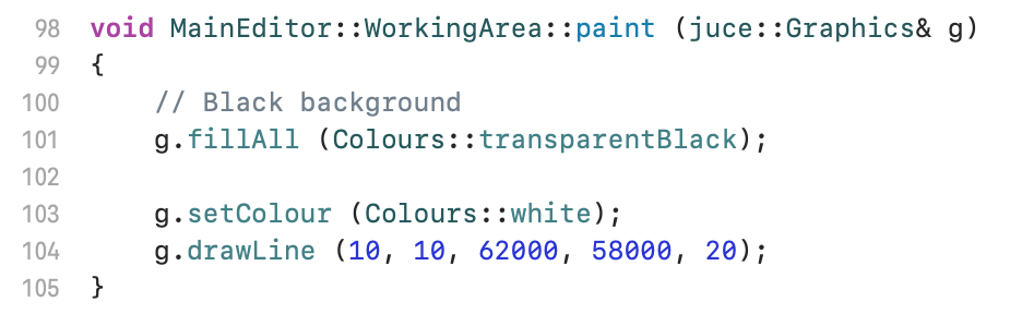
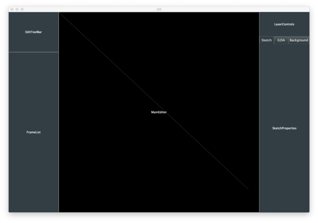
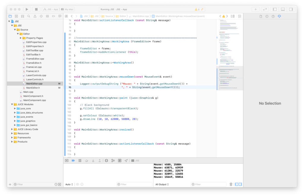
We can then confirm that scaling is being handled for us a couple of ways. First, inside our WorkingArea class we can draw a line that would be way too long to fit onscreen if we were not scaled:
The drawline parameters are x1, y1, x2, y2, linewidth. We have to make the line 20 units wide so that we can see it scaled down. It is faint, but we can see that our line was drawn from very close to the top left to bottom right:
But what about user input? We can override a method in our WorkingArea class and print out mouse coordinates to the debugger:
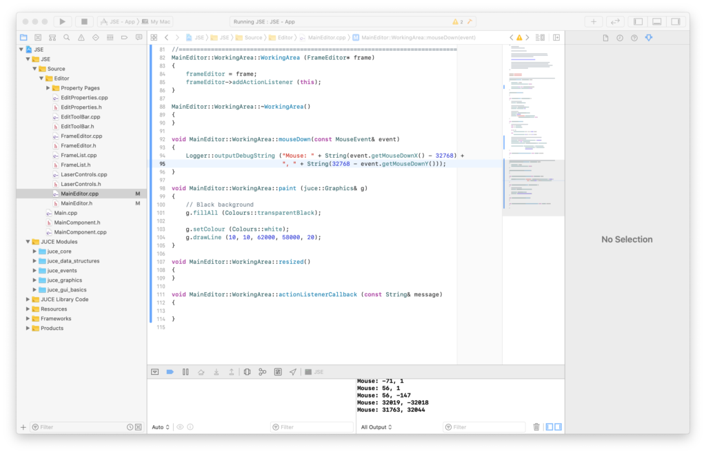
Although we are clicking on a relatively small display window, we are getting coordinates scaled up to 16-bit. JUCE is 0,0 = top left. ILDA is 0,0 equals center, so to get mouse clicks as ILDA coordinates we need to apply an offset:
Clicking near the center gives us values near 0,0 and the quadrants are all the correct polarity for ILDA coordinates.
What might not be obvious from above is that this scheme keeps working even if we don’t scale our WorkingArea component to fully fit on screen and centered in our MainEditor component. We could zoom in and pan. Only the portions that fit in the visible area of our MainEditor component can be seen and clicked on, but the mouse input and display scaling will keep working in our ILDA sized space.
So far so good, but a scheme like this works best when everything being referenced and/or edited is drawn in the same scale context. That would include things like artwork we want to trace. If we draw the image in another component without the AffineTranform scaling applied, there can be small rounding errors how things stack up and align. You wouldn’t want to zoom in super close to trace a curve, then zoom out to find that what you had just drawn has shifted slightly away from the reference. If possible, we definitely want to draw even our reference images in this big 16-bit sized component.
But what will happen if we scale a reference image up to 62535 in size, then scale it back to fit on our screen? Will it get all distorted? JUCE has pretty good image scaling code, but the only way to know for sure is to put it to the test.
You might have noticed that our Properties rectangle already has tabs for our three editor layers. JUCE has a TabbedComponent class, so I went ahead and used it. Next I throw in some controls for our Background (Reference) layer using some JUCE UI control components. You can re-skin these components with something called the LookAndFeel class, or even override their paint methods outright, but we’ll just run with the stock versions and a few color tweaks.
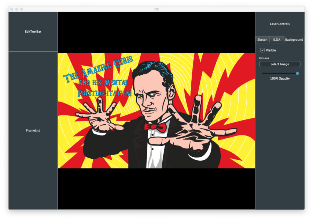
I started simply, with just a button to pick the image, a way to toggle visibility on and off, and a slider to control the image opacity. I picked an image with lots of curves and squiggles to make sure I was happy with the rendering quality.
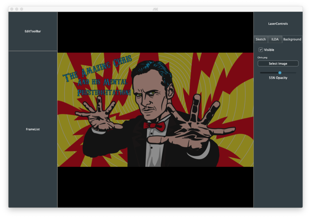
I used the JUCE drawImage method that scales to fill a rectangle and gave our entire 65536×65536 component as the target. I tried other images as well. They all scaled up and back down nicely. Of course, this image blasts in your face, hence my immediate addition of an opacity control:
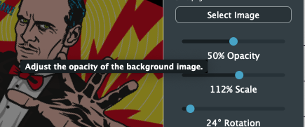
But there is another version of drawImage that uses… you guessed it, an AffineTransform! So, what the heck, I added scale, rotation, and positional offset controls. These might actually be handy if you are trying to animate someone’s static logo.
I also added some placeholder plumbing so that we are editing a Frame container class. But we really do pick up a lot of goodies in a hurry using JUCE. For example, tooltips:
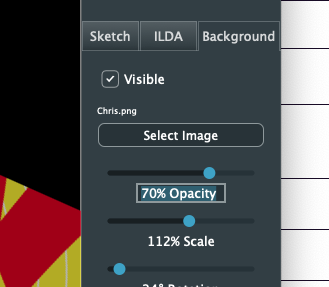
If you hover the mouse, the tips pop up with just an extra line of code on our part. The sliders also sense mouse speed, so you can dial in every possible number, even though the sliders themselves are less than 200 pixels wide. You can also just click on the text under a slider:
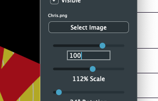
It highlights. Type in the new desired value as a number:
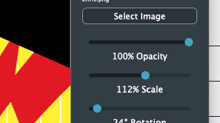
And hit enter:
Since we are an editor, the other thorny issue we want to resolve up front is Undo/Redo. These schemes are very hard to retrofit after an editor is otherwise written. Again, JUCE gives us a big leg up, but I’ll have to cover that next time!
In our last post we sketched out a simple editor design. Now we need to turn it into code we can compile. We want to be able to build and run as a native application on OS X, Windows, Linux, and iOS (iPad). All platform vendors would really like you to write for just their platform, so they all have their own preferred language, C# for Windows, Objective C or Swift for OS X, etc. Even in the Linux world, Android is a non standard JAVA framework on top of Linux.
But all the platforms have a dirty little secret. They all generally still support C++ and probably will for years to come. Why? Games. Most high performance game code is written in C++ and that industry still has the leverage to keep even Apple and Microsoft somewhat in check.
But native C++ code for each platform would normally be quite different. Each handles windows, cursors, controls, messaging, and etc. differently. What we want is core C++ code that accesses generalized operating system services (an ‘OS abstraction layer’ if you will), then native drivers to compile and provide those generalized services on each platform. I can personally attest it is possible to do this from scratch, but it is a crapload of work.
Fortunately a few good free options are available to us. One popular option is Qt (pronounced “Cute”). Each time I start one of these projects I take another quick look at it. It’s got a big community, a very permissive license agreement, and is certainly capable of what we want to do but… I just don’t like the coding style or framework design.
So, once again, I’m going with JUCE. A framework very popular in the music industry. I’ve actually been using JUCE for various projects for years and contributed a number of fixes and classes back when it was all maintained by one guy, Jules Storer. It has gotten a bit big and complicated too, but I just find most the source code vastly easier to navigate and quickly understand.
The latest version of JUCE is 6.0 (released just a few weeks before I wrote this). If a program is non commercial and open source, as this one is, no license is required. However, if you make changes and build your own version you must either enable the “Made with JUCE” splash screen or purchase a suitable JUCE license. I actually have a license, so any binary builds I distribute here will have the splash screen disabled. But please do honor the licensing agreement!
There are tutorials and books on JUCE, so I’m not going to reinvent that wheel. Likewise, I’m not going to take a stab at teaching you C++, though even if you know C++ I’d recommend reading something like Scott Meyer’s “Effective C++“. Storer clearly embraced the RAII (resource acquisition is initialization) methodology in much of the JUCE library.
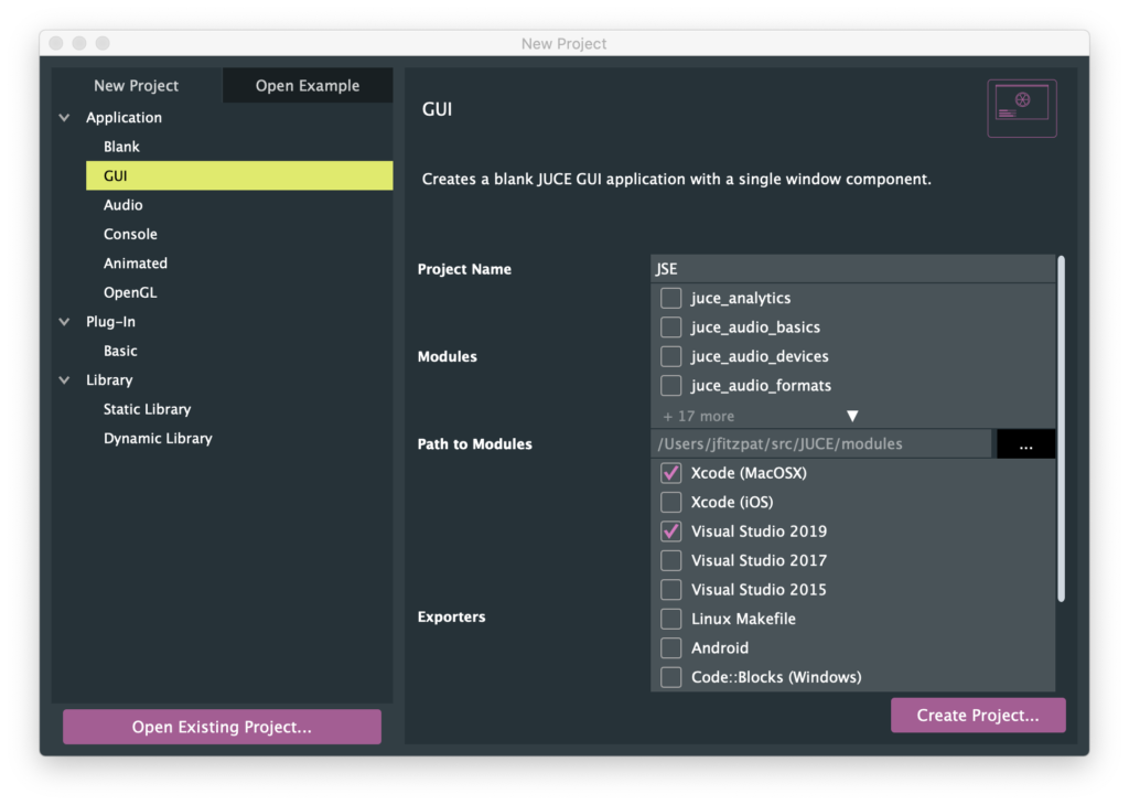
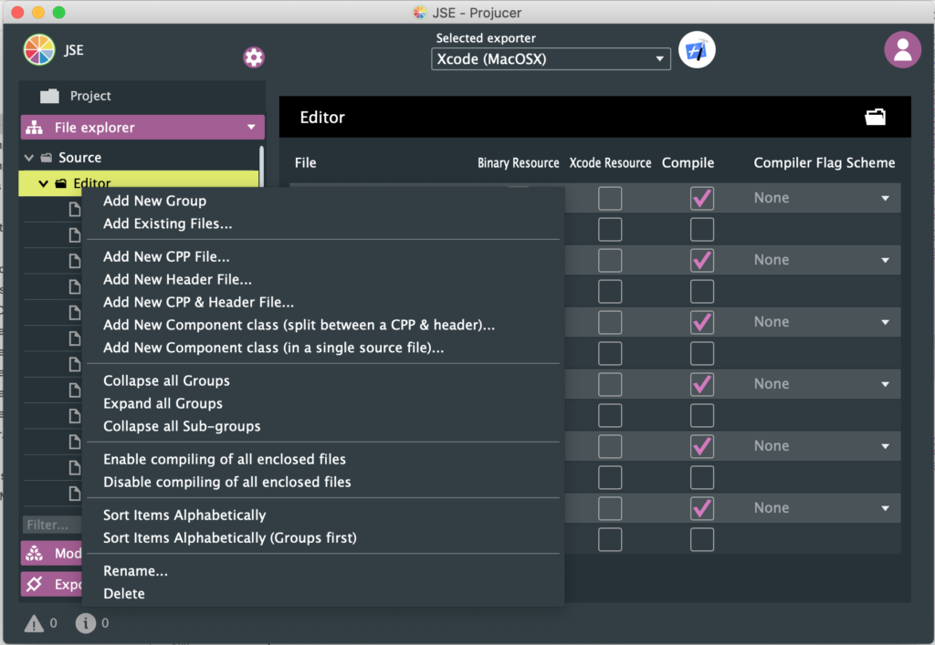
We’ll just jump in with a tool called the Projucer (previously the Jucer, hence the orange slice icon). You can download the Projucer as a binary for your platform or just build from the source included with the JUCE library (what I normally do). The tool is a platform independent way to create a project and maintain the files in it. It then can export project files for the XCode on Mac, Visual Studio on Windows, etc. There is also a simple graphical editor which can be handy for putting together basic graphical UIs, but we won’t be using that in this post.
To kick off our simple editor I’m picking a new GUI project, giving it the name “JSE”, and picking Xcode (MacOSX) and Visual Studio 2019 as our first exporters (we can add more later).
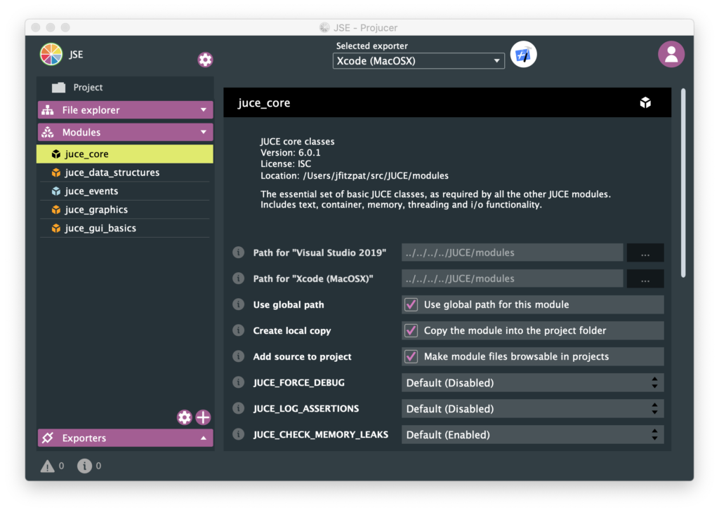
One default I am going to change is I am turning on “Create local copy” for each of the 5 JUCE modules that are in our project so far. This puts all the source code used by our application together, so it all goes into source control as one complete set of files. This helps insure that we can build or application later, even if we haven’t worked on it for awhile and something in JUCE has changed.
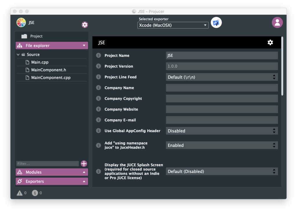
One other change from default is in the global project properties, accessed via the little gear icon at the top of the window. Obviously we’ll want to populate many of these fields, but I’m switching “Add ‘using namespace juce’ to JuceHeader.h” to Enabled. If you don’t have this turned on you need to use all JUCE classes and data types with the prefix “juce::”. If you are using a bunch of other third party libraries this is a good way to avoid name collisions, but it is a lot of extra typing, so I’m adding the namespace to any file we include “JuceHeader.h” in.
If we click the Xcode looking icon at the top, our project is saved, a project for Xcode is exported, and XCode (free for download from Apple) is opened with it. Building and running our project we get:
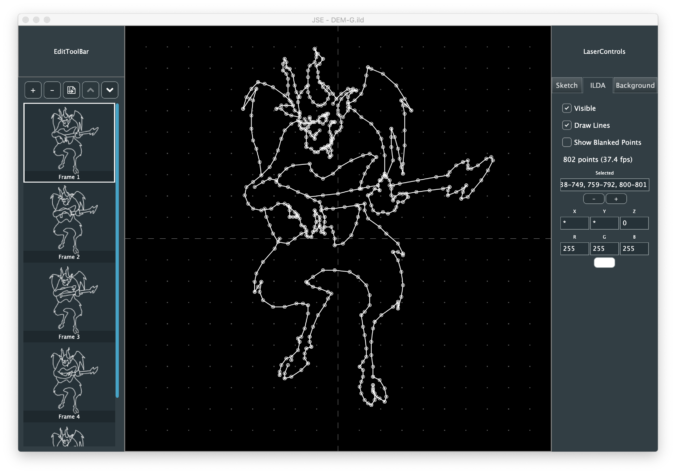
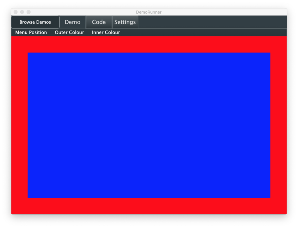
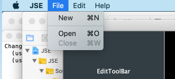
In addition to books, tutorials, and the reference documentation. Another good place to figure out how to do things is JUCE is the “DemoRunner” application, pictured at the top of this post. You can browse demos on the left and select them. Some are a lot snazzier and more engaging than others, but let’s pick something mundane, like Menus:
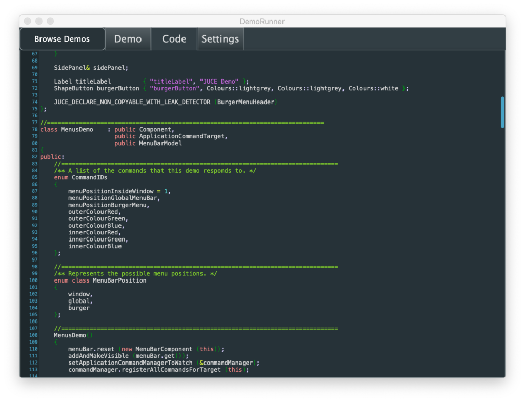
The sample lets you put the menu different places, top of the screen (OS X only), top of the window, or in a side bar. Then the positioned menu let you change colors for the frame and center rectangle. Like all the samples, there is a Code tab that lets you examine the relevant source code without having to search in the compiler:
The demo introduces us to some classes we might expect, like MenuBar, MenuBarModel, and PopupMenu. If you are at all familiar with the “Model-View-Controller” design template favored by Apple for iOS and frameworks in OS X, these should be pretty clear. But the demo also shows how to use another optional class called the ApplicationCommandManager, which lets you manage application operations and any hot keys for them in a centralized way.
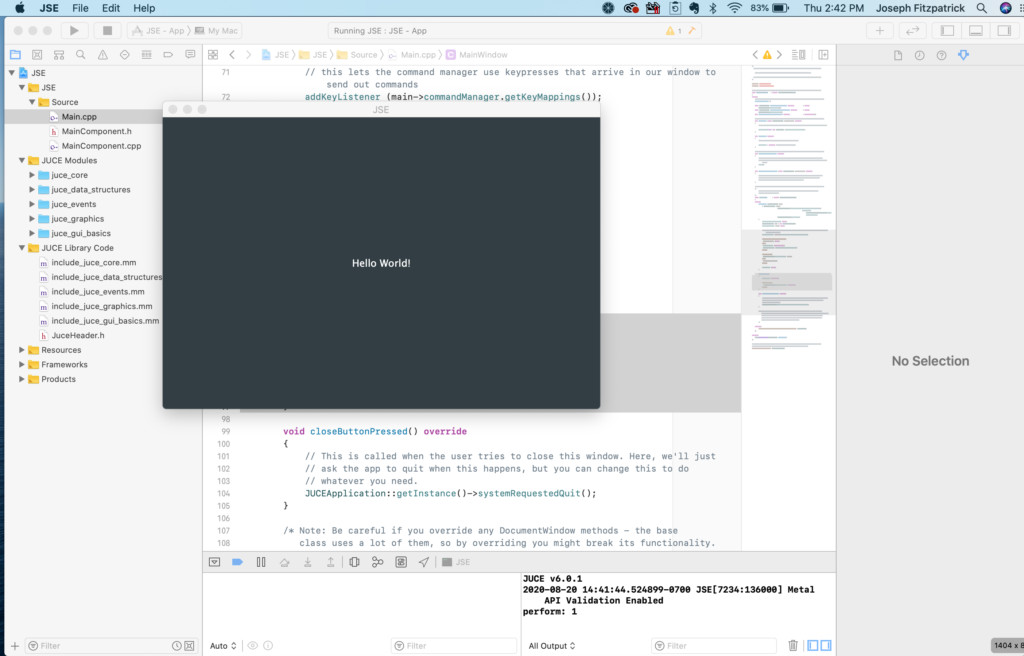
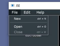
Using the demo as a guide, it was very straightforward to add a native OS X menu with some placeholder operations to our app and check that both making a menu selection and pushing hot keys trigger the “perform: x” debug message I added:
Unlike the demo, I actually used the MenuBar instance that came with our top level window. I also added this conditional code to our MainWindow constructor in Main.cpp:
If we are building for Mac, the menu goes at the top of the screen. Otherwise, it goes at the top of our window. All the sample commands were done via an ApplicationCommandManger, not directly responding to the selection function in our MenuBarModel class. We’ll see one advantage to this in a bit.
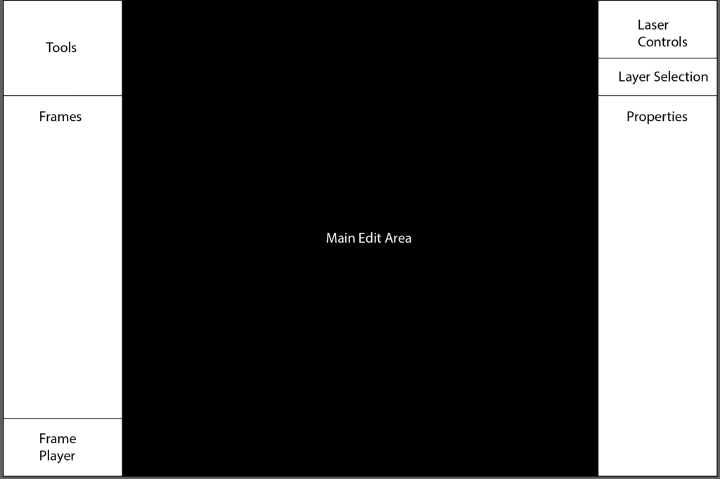
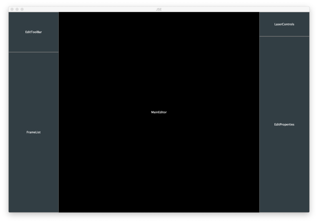
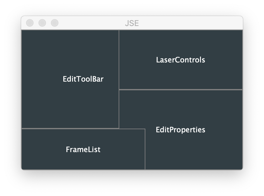
Now that we have a simple app running and have dabbled at adding functionality based on a JUCE demo, it is time to start making this sketch from our design come together:
The basic UI building block in JUCE is a “Component”. All the UI controls, like Button and ListBox in JUCE are classes that inherit from Component and then add specialized functionality. Components can contain other components as children. So we can do something similar and make our different screen areas their own component.
Going back to the Projucer we can right click in our source tree and add skeleton component classes as files:
I went ahead and added “New Component class (split between a CPP & header)” for most our main areas. Skeletons created this way draw a gray boarder and put the class name in the middle by default.
But these classes also need to somewhat work in unison. When a new frame is selected, any properties displayed must update, and etc. There are different ways to manage this, but I’m going with a service_provider-broadcast model. I’m creating a non component (not visible) class called FrameEditor. This class will inherit from a JUCE class named ActionBroadcaster.
Our visible components will, in turn, all inherit from a JUCE class named ActionListener. These GUI classes will ask FrameEditor to do the work and FrameEditor will broadcast messages that operations have occurred so that the other components can respond accordingly.
Our MainComponent that was created for us initially (the one that says “Hello World!” on the screen), will stick around as the frame that holds all our newly created components. We start by including the related header files and added pointers for each of our component classes to the definition of MainComponent:
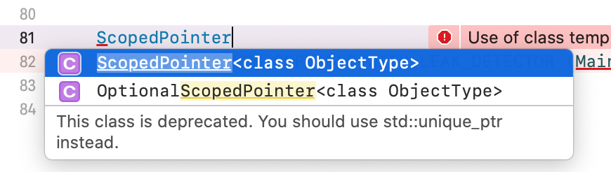
The answer is RAII. JUCE has a template class called ScopedPointer. That class automatically deletes the class it points to when the template ‘pointer’ class is reassigned or deleted. This gets rid of the memory leak problems typically associated with “new” and “delete” in C++. This functionality was finally added to the C++ standard library when the 2011 standard was ratified, so if you try to use ScopedPointer now you get warned you should use the std::unique_ptr class instead:
Next we add this to our MainComponent constructor:
    // Shared frame editor worker class
    frameEditor.reset (new FrameEditor());

    // GUI components
    toolBar.reset (new EditToolBar (frameEditor.get()));
    addAndMakeVisible (toolBar.get());
    laserControls.reset (new LaserControls (frameEditor.get()));
    addAndMakeVisible (laserControls.get());
    editProperties.reset (new EditProperties (frameEditor.get()));
    addAndMakeVisible (editProperties.get());
    mainEditor.reset (new MainEditor (frameEditor.get()));
    addAndMakeVisible (mainEditor.get());
    frameList.reset (new FrameList (frameEditor.get()));
    addAndMakeVisible (frameList.get());
We create an instance of our service provider class, then pass in a pointer to it as a parameter as we create each of our GUI components. This way they can use it to perform operations and (optionally) register for broadcast messages when operations have occurred. The addAndMakeVisible calls add each component as a child of our MainComponent and make them visible.
Last, we need to position the children when our MainComponent is resized:
Most the components are anchored to the right or left of the container. I Also tweaked our MainEditor component so that it’s paint function makes the background black. The other components still have their default (gray outline w/name) behavior. When we run the app, it looks a lot like our sketch:
As we play with with adjusting the size and going full screen, it looks pretty good, but there are two obvious problems. One, we can make it too small to be useful:
That’s easy enough to fix, we can constrain the minimum size for our window in the MainWindow constructor in Main.cpp:
You can also do things like constrain aspect ratio, but keeping us 640×480 or larger works for now.
The other problem is that our main editor area isn’t always square. ILDA X/Y coordinates are a 65535×65535 grid. So our working area, at least while we show the full field, is always square. So let’s change our MainEditor class so that it calculates a centered, square working area based on width and height each time we are resized and draws an outline of the working area every time we are painted:
void MainEditor::paint (juce::Graphics& g)
{
    // Black background
    g.fillAll (Colours::black);

    // Outline working area
    g.setColour (juce::Colours::grey);
    g.drawRect (activeArea, 1);

    // Class name
    g.setColour (juce::Colours::white);
    g.setFont (14.0f);
    g.drawText ("MainEditor", getLocalBounds(),
                juce::Justification::centred, true);
}

void MainEditor::resized()
{
    // Figure out our working area
    auto w = getWidth();
    auto h = getHeight();

    if (w > h)
        activeArea.setBounds ((w - h) >> 1, 0, h, h);
    else
        activeArea.setBounds (0, (h - w) >> 1, w, w);
}
Now the working area is indicated and we can see dead space is either top/bottom or left/right depending on our window’s aspect ratio:
Yes, it’s just squares and text, but look what happens when we go to Windows and compile in Visual Studio 2019 (free for download from Microsoft):
Huzzah! Our app already compiles and runs natively in multiple operating systems with minimal effort. As we go we will have to continue to put in some tweaks to maintain a good native feel for each platform, but JUCE handles a lot. Case in point, check out the shortcuts in our in window menu under Windows:
Notice they use the key, normal for Windows. But if look at the menu when we build for Mac:
The shortcuts use the Apple Command key, normal for OS X. This is one of the details that ApplicationCommandManager just took care of for us automatically.
The system used to do it, but the vendor made a conscious decision to drop support for the open standard. We are going to need graphics and I must admit that my first inclination was to just cheat. The commercial system still talks to an ILDA table so I could just capture the data coming out of it and store it in ILDA files, either sampling in analog or capturing the data just upstream where it is written in digital form to the DACs. But the system is 12 bit output, 1/16th the resolution we want.
Capturing at the ILDA projector end is also inherently X, Y, and color only. There is no reason to transmit Z data to the scanners, so we’d still need a way to add some Z data information to our graphics for some of the effects Marty wants to do with our new fangled rolling shutter gag.
It’s likely that the commercial system handles data at a higher resolution and includes Z information at the host end. It reads files from a prior system that was 16 bit. And it still imports ILDA standard files which are also 16 bit. But the file format is proprietary and what they describe as “secure”. No, it’s not particularly secure, but it’s part of a commerce system. Content creators can key content to just certain projectors. If I show everyone how to bypass that security I’d be potentially hurting show programmers and artists. Also, it just would feel sleazy, on par with being contributors to the ILDA standard and then not bidirectionally supporting it…
Anyway, once I realized I couldn’t (ok, wouldn’t) just cheat, I asked online in a Laser Entertainment group on Facebook what everyone was using for ILDA graphics content. I was actually surprised by some of the answers. The commercial system that stopped supporting export seems to be pushing a line that the ILDA format is 30 years old and would hold the industry back. But it is 16 bit X, Y, Z data and 24 bit true color RGB information. A frame can hold up to 65535 coordinates, which would need 600 kHz scanners to display 10 times a second. The fastest scanners I could find to buy are 1/10th that speed.
A file can also contain up to 65535 frames, about 36 minutes of content at 30 frames per second. Yes, it’s still barebones and simple, but good enough for Marty’s needs. And there were at least a few responses online that indicated other people might find it helpful. So…
Time to do a simple, open source editor. “JSE”. I must admit that I did not spend any real time looking at the existing commercial editors. I took some online comments, had a few conversations with Marty, and sketched out this:
Tools are what you might expect in, say, Adobe Illustrator: Pen, Ellipse, Selector… They will change based on the layer selected (see below).
Frames displays and lets you navigate the frames in the file. I envision something along the lines of the slides display in Power Point.
Frame Player is simple transport controls for playing the slides as an animation.
Laser Controls are for displaying and editing on a projector. This is also where you tell the system how fast you plan on scanning a given frame.
Layer Selection is to pick one of the three layers available in the Main Edit Area.
Properties is where you view and set properties for the current layer and any selected items in it.
The Main Edit Area is where you edit the currently selected frame. All work occurs on one of three layers.
The simply layer system I came up with is this:
The Reference layer is in the back and is a place to load reference artwork, like a PNG or BMP file. You can scale and rotate it and load different reference artwork for each frame.
The ILDA layer is the connect-the-dots sequence that is actually stored an ILDA file. This layer is a simple editor in its own right. You can insert points, delete them, set their visibility and color, etc. Groups can be selected and transformed (scale, rotate, etc.) This is the only layer that is not ‘fixed’ in 3D space. It can be rotated and positioned relative to the other two layers.
Sketch layer is for non artistically inclined people like me. It holds “paths” made up of straight lines and cubic bezier curves. Paths have attributes like color and visibility and can be individually or collectively “stroked” (converted to coordinate pair ‘dots’) on the ILDA Layer.
Based on what I have been told, most commercial editors have some form of polygon tool for straight lines, but I really like the model of the Pen Tool in Adobe Illustrator. Click for straight lines, click and drag for curves, adjust the control points for the bezier curves with little control bars:
When you draw a circle or ellipse in Illustrator you wind up with four anchor points and bezier curves between them:
You actually can’t draw a perfect circle with cubic bezier curves, but you can get very close with a concept called ‘the kappa‘. Bezier curves are also pretty computation friendly for finding points and distances along the curve, so great for our purposes generating ILDA content.
In addition to adding curves and control handles, another thing I believe I am doing differently is keeping sketches, each with one or more paths, around. My understanding is that with most editors you set options, like point spacing, anchor and blanking point preferences, etc. and ILDA type coordinates are generated as you use each tool.
I’m thinking along the lines of Autodesk Inventor, where you have a persistent ‘sketch’ and Adobe Photoshop, where the ‘path’ is separate from the ‘stroke’, or actual rendering. My reasoning is two fold.
Getting a good ‘stroke’ (ILDA points) can be a trial and error process. You probably want to trace the reference drawing once, then try changing settings for the various paths and generating points until you get something that looks good.
If you are making a simple animation of, say, a logo you probably want to duplicate the previous frame and modify the sketch objects, not retrace from scratch.
Being able select which path(s) to stroke-to-dots is an extension of #2. You might want to to adjust the ILDA layer and stroke parts of the image at different angles in 3D space.
I have quite a few other thoughts, but this covers the basic concept. As you may have guessed from the images at the top of the post, I have already done coding tests for many of the concepts and have started framing in the actual application.
We want an app that can run natively on OS X, Windows, and and iPad pro, so in the next post I will introduce you to JUCE!