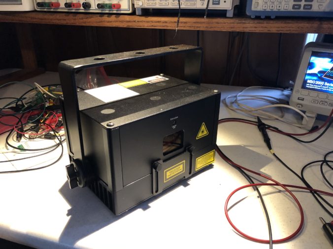
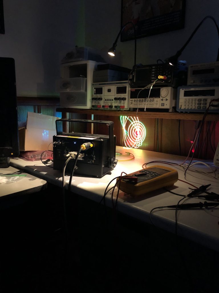
Thanks to Marty Canavan from YLS Entertainment, I now have a borrowed, albeit small, modern laser projector. One thing that has definitely changed from my time in the laser penalty box 35 years ago is the lasers themselves. This little guy puts out several watts of red, green, and blue laser light while being air cooled and running on wall 120V.
In the bad old days, lasers that put out a few watts of white light would be a 4′ water cooled glass vacuum tube with krypton gas, a big electromagnet, and a 560V transformer hooked to three phase power. But enough Grandpa Simpson venting! Let’s get this puppy working.
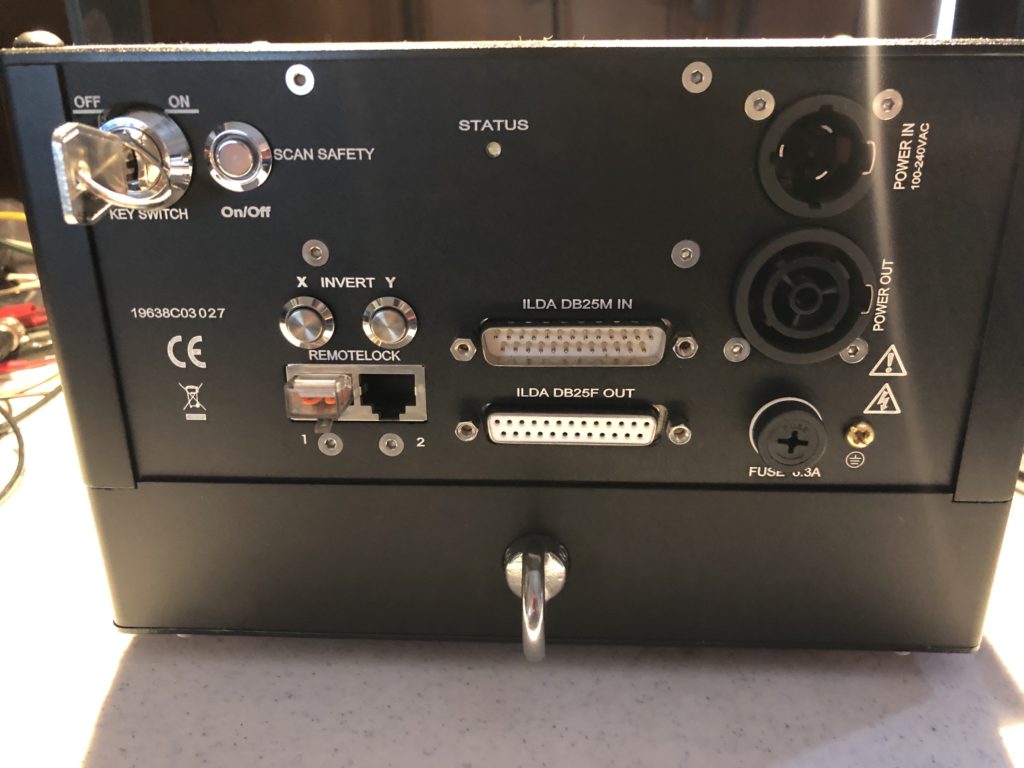
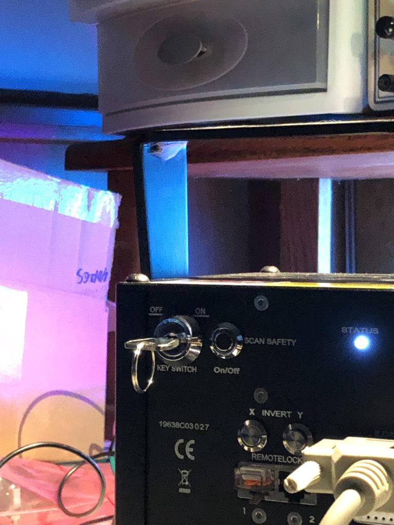
The back panel seems pretty busy, but the only three things we’ll worry about now are power in – which is 120V, the on-off key-switch, and the connector labelled “ILDA DB25M IN”.
ILDA stands for “International Laser Display Association“. It is a trade group that was getting started just as I left the industry. They publish a number of standards, including one for the projector connector above, which is here.
Since the standard is from 1999 and the industry is small, I always like to double check the standard against actual industry practices, so YLS also loaned me an existing scanning system. Alas, I ran into a few hiccups getting it going.
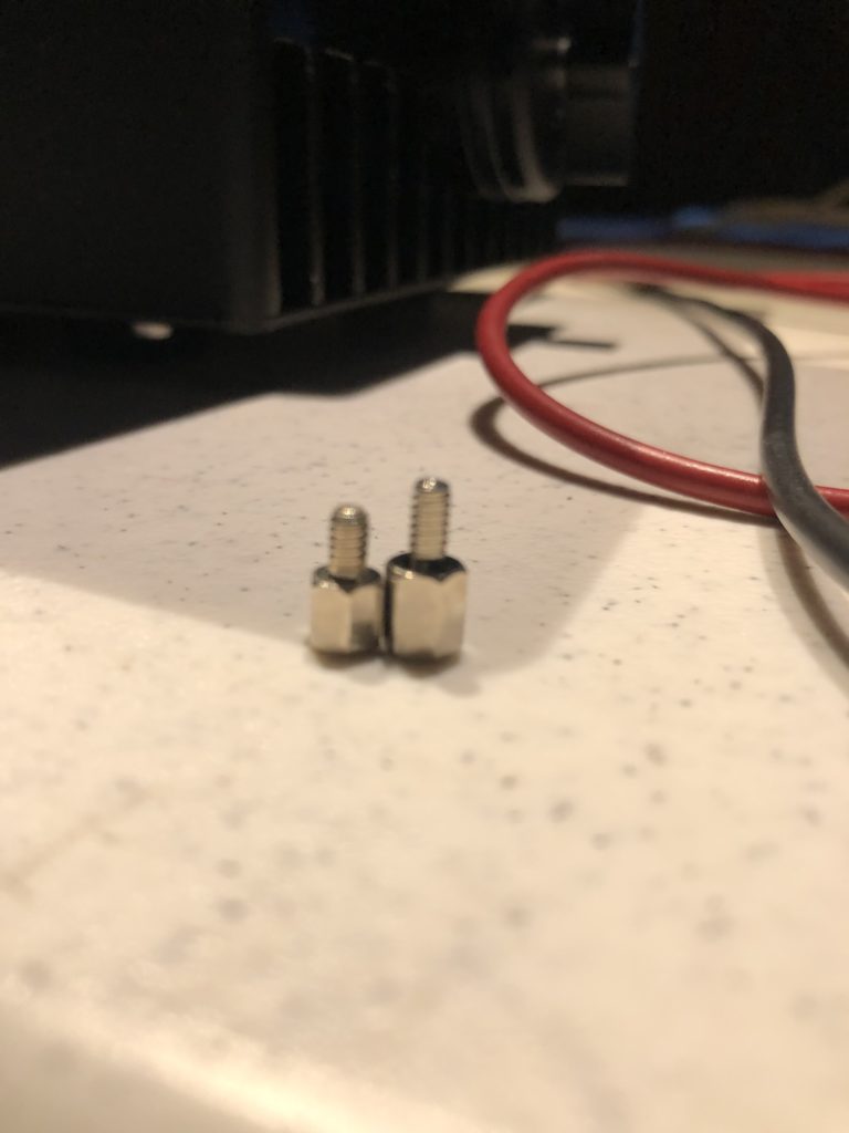
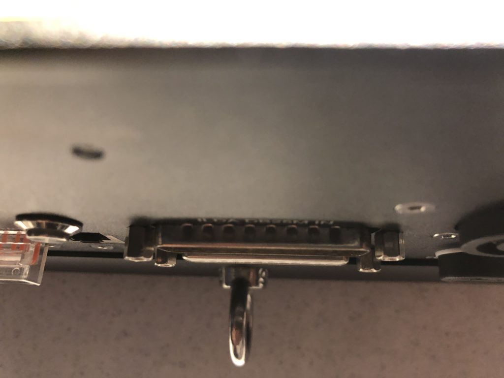
First, the DB25 connector did not fit correctly, so not all control signals were reaching the projector. It turned out that the small DB connector threaded standoffs were not all the same height:
Once I fixed that I had to reach a negotiated settlement with the spider who had taken up residence on the yoke (something tells me this piece of equipment hasn’t been seeing a lot of field time):
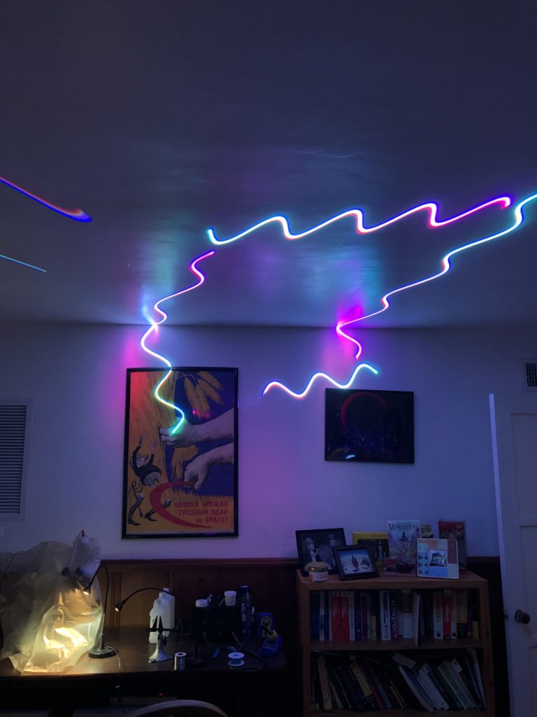
With the connector fixed and my new lab mascot settled in, I was finally making bright squiggles!
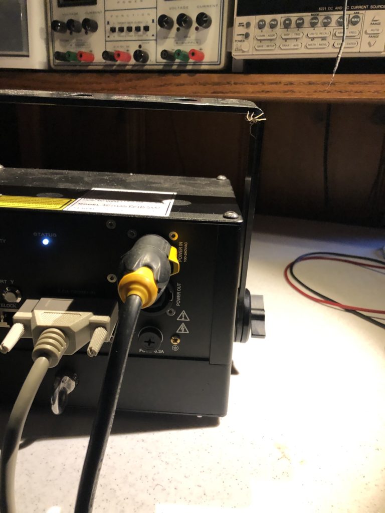
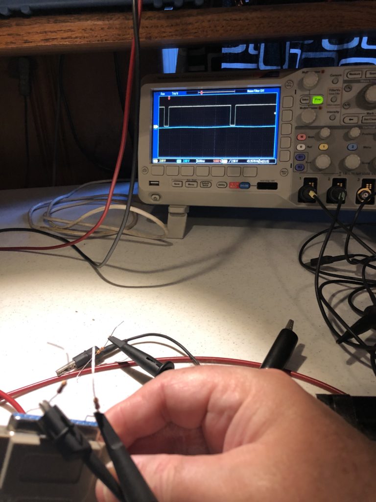
So turned the projector around and started examining signals with an oscilloscope. The X and Y signals were exactly as specified. A 10V differential signal, with the + and – signals both going +5V to -5V relative to signal ground:
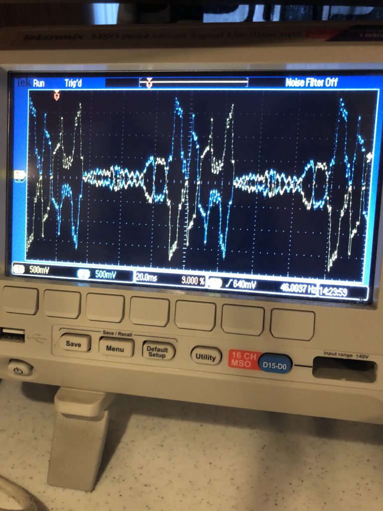
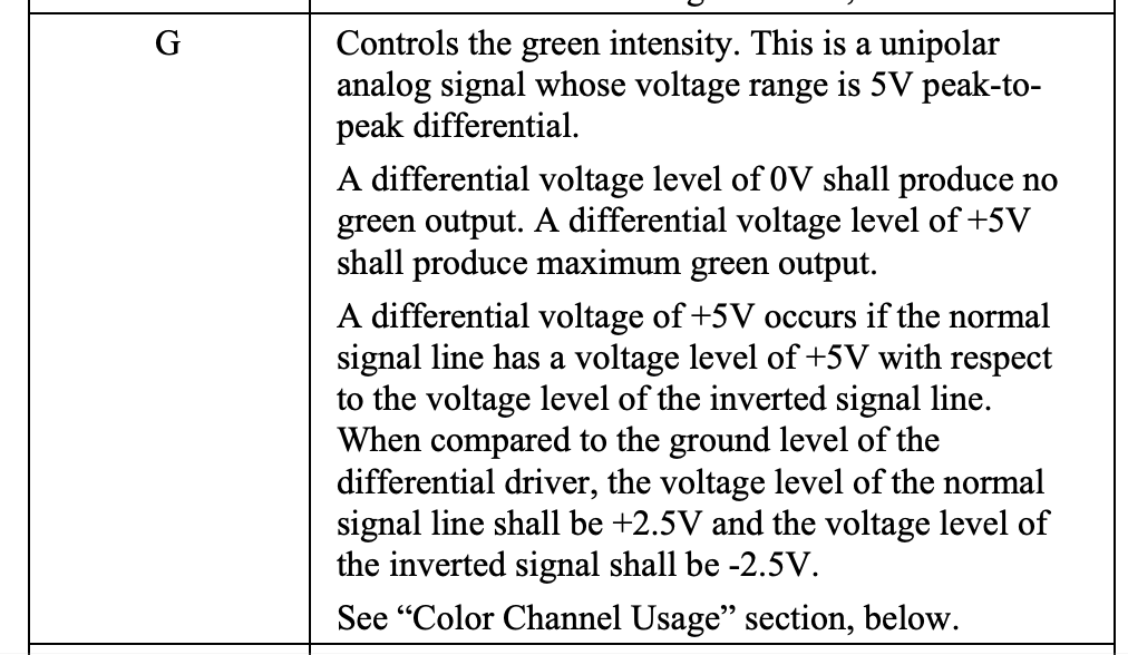
Intensity/Blanking, Shutter, and the Interlock Pins were also all exactly as specified. The only surprise was the color channels. The specification calls out a 5V differential signal with the + and – signals outputting a +/- 2.5V bipolar signal relative to signal ground:
However, there was no deflection on the R-, G-, or B- signals and the R+, G+, and B+ signals all adjusted from 0 to 5V DC relative to ground:
This is still a 5V differential, but does not honor the bipolar properties called out for in the specification. I used a multimeter set to resistance to check for continuity between the negative color inputs and signal ground and it seemed clear that the projector is using a differential input circuit, so I tested a color signal by feeding in +2.5V and -2.5V to the R differential pair and it appeared to work fine.
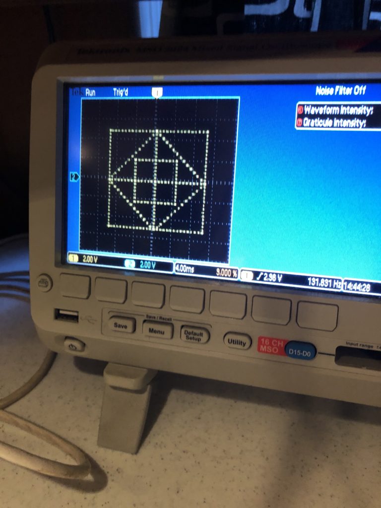
With things up and running and and the signals all confirmed, I took a quick at the scanning/camera problem I am trying to solve. The oscilloscope has something called ‘persistence’. Traced lines linger awhile, so when we take a photo with a rolling shutter, we get the whole image, but when photograph the scanning laser beam, we only get a part of the image:
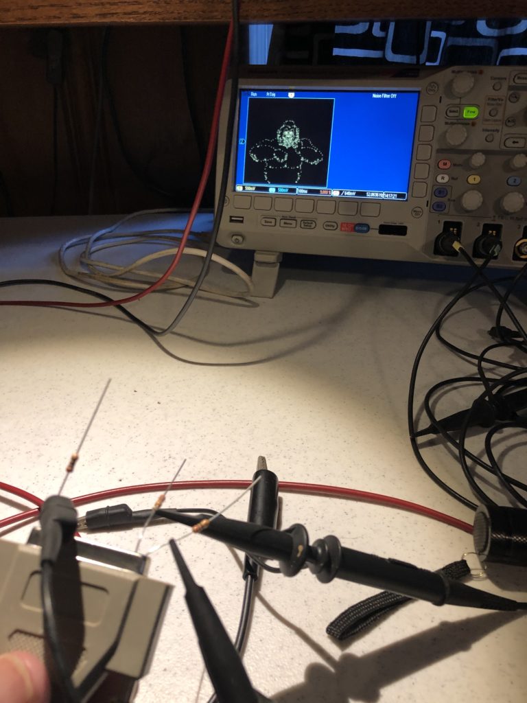
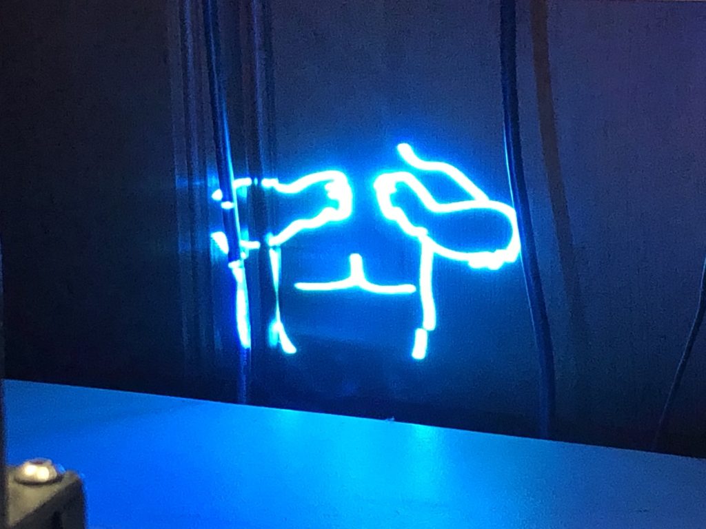
This could make for some interesting effects with projected geometrics, but with the existing scanning system tested, the control over image scan rate is too course and the scans themselves are not stable enough. That is, you can’t dial in the exact speed you need and the system doesn’t hold speed consistent enough to get the desired effect.
So, next up, we are going to have to start putting together a control system!
Leave a Reply